DYNAMIC RADAR CRUISE CONTROL SYSTEM
-
FUNCTION OF MAIN COMPONENTS
-
The main components in the dynamic radar cruise control system have the following functions:
Component Function Millimeter Wave Radar Sensor Assembly Radiates millimeter radar waves forward, uses the reflected waves to detect the presence of a vehicle traveling ahead, the vehicle-to-vehicle distance, and the relative speed, and then transmits this information to the driving support ECU assembly. Forward Recognition Camera Detects lane markers and objects on the road ahead using the image captured by the monocular camera and sends the information to the driving support ECU assembly. Camera Heater (Forward Recognition Hood with Heater Sub-assembly) The camera heater is heated according to signals from the forward recognition camera. Driving Support ECU Assembly
-
Determines presence of a preceding vehicle based on information from the millimeter wave radar sensor assembly and the forward recognition camera.
-
While the system is in vehicle-to-vehicle distance control mode, the driving support ECU assembly detects the vehicle ahead based on signals from the millimeter wave radar sensor and forward recognition camera. Then, the driving support ECU assembly calculates the acceleration or deceleration rate required in order to attain the target vehicle-to-vehicle distance, and outputs a request signal to the hybrid vehicle control ECU.
PCS Buzzer (Skid Control Buzzer Assembly) Sounds upon receiving a signal from the driving support ECU assembly and alerts the driver that the distance between vehicles is short. Cruise Control Switch ON-OFF Button
-
Turns the cruise control system on and off.
-
Vehicle-to-vehicle distance control mode becomes be activated immediately after the main switch is turned on. The mode shifts to constant speed control mode by pressing and holding the button more than 1.5 sec.
CANCEL Switch A cancel signal is output to the hybrid vehicle control ECU when this switch is operated. +RES Switch The acceleration function and resuming of a preset speed can be performed by operating this switch. A signal is output to the hybrid vehicle control ECU when this switch is operated. -SET Switch The deceleration function and vehicle speed setting resume signals are output to the hybrid vehicle control ECU when this switch is operated. Steering Pad Switch Assembly Vehicle-to-vehicle Distance Control Switch While the system is in vehicle-to-vehicle distance control mode, the driver can operate the distance control switch to select the vehicle-to-vehicle distance in 3 levels: long, middle, and short. Hybrid Vehicle Control ECU
-
Controls the dynamic radar cruise control system in accordance with signals from switches, sensors, and the driving support ECU assembly.
-
If the hybrid vehicle control ECU detects a malfunction in the dynamic radar cruise control system, it will store DTCs (Diagnostic Trouble Codes).
Inverter with Converter Assembly MG ECU Built into the inverter with converter assembly. Controls the motive force of MG2 in accordance with signals from the hybrid vehicle control ECU. Hybrid Vehicle Transaxle Assembly MG2 Generates motive force for the wheels. ECM Actuates the throttle control motor in accordance with the signals from the hybrid vehicle control ECU. Brake Booster with Master Cylinder Assembly Skid Control ECU
-
While the system is operating in vehicle-to-vehicle distance control mode, the skid control ECU performs brake control in accordance with request signals from the hybrid vehicle control ECU.
-
Transmits signals such as wheel speed and estimated vehicle acceleration to the hybrid vehicle control ECU.
-
Illuminates the stop lights during brake control.
-
Sends the VSC and TRC control status to the hybrid vehicle control ECU.
Combination Meter Sub-assembly Cruise Control Indicator Light
-
Based on a cruise control indicator light operation signal sent by the hybrid vehicle control ECU, the combination meter assembly illuminates the cruise control indicator light (constant speed control mode) or cruise control indicator light (vehicle-to-vehicle distance control mode) when the cruise control system has been turned on using the cruise control switch.
-
Based on a cruise control indicator light operation signal sent by the hybrid vehicle control ECU, the combination meter sub-assembly turns off the cruise control indicator light if a malfunction occurs in the cruise control system.
Cruise SET Indicator Light Illuminates when the vehicle speed is set. Buzzer If the driving support ECU assembly detects automatic cancel or warning signals while the vehicle is operating under cruise control, this buzzer sounds to inform the driver. Multi-information Display
-
Displays a warning message to alert the driver in accordance with a signal provided by the hybrid vehicle control ECU.
-
During dynamic radar cruise control operation, the multi-information display receives signals from the hybrid vehicle control ECU in order to display the system conditions.
Throttle Body Assembly Throttle Control Motor Adjusts the throttle valve opening angle in accordance with signals from the ECM. Throttle Position Sensor Detects the throttle valve opening angle and outputs it to the ECM. Speed Sensor Detects the wheel speed of each of the 4 wheels. Accelerator Pedal Sensor Assembly Detects the accelerator pedal depression degree and outputs it to the hybrid vehicle control ECU. Stop Light Switch Assembly Detects brake pedal depression and transmits its signal to the hybrid vehicle control ECU. Shift Lock Control Unit Assembly Shift Lever Position Sensor Detect the shift lever position and transmit signals to the hybrid vehicle control ECU. Spiral Cable with Sensor Sub-assembly Steering Sensor Detects the angle and direction of steering and transmits signals to the driving support ECU assembly. Airbag ECU Assembly Yawrate Sensor Detects the yawrate of the vehicle and transmits signals to the driving support ECU assembly. Central Gateway ECU (Network Gateway ECU) Gateway function of CAN communication. -
-
-
FUNCTION
-
Function List
-
The control of the dynamic radar cruise control system varies depending on the mode:
A: Constant Speed Control Mode
B: Vehicle-to-vehicle Distance Control Mode
Function Outline Mode A B Constant Speed Control Controls the motive force through the hybrid vehicle control ECU and skid control ECU assembly, and adjusts the vehicle speed to the set vehicle speed. ○ ○ Deceleration Control Performs engine, MG2 and brake control in order to decelerate the vehicle so that the vehicle-to-vehicle distance between the driver's own vehicle and the vehicle ahead is maintained at the set distance. - ○ Follow-up Control After performing deceleration control, the driver's own vehicle follows the vehicle ahead in order to maintain the proper vehicle-to-vehicle distance. The actual distance maintained for each distance level (long, medium and short) varies in accordance with vehicle speed. - ○ Acceleration Control Accelerates the vehicle in order to attain the set vehicle speed if the vehicle ahead or the driver's own vehicle has changed lanes. - ○ Set Control When the cruise control system has been turned on using the ON-OFF button on the cruise control switch, either of the relevant vehicle speed conditions shown below is met, and the cruise control switch is moved to the -SET side and released, the driving support ECU assembly stores the vehicle speed and maintains the vehicle constantly at that speed. ○ ○ The vehicle is traveling at a speed within the range of approximately 40 km/h to 200 km/h (25 mph to 125 mph). ○ - The vehicle is being driven at an approximate speed of between 50 km/h to 180 km/h (30 mph to 110 mph). - ○ Low Speed Limit Control The low speed limit is the lowest speed that cruise control can be operated at and it is designed to be approximately 40 km/h (25 mph). The cruise control system cannot be operated below that speed. If the vehicle speed drops below that speed while the cruise control system is set and working to maintain vehicle speed, speed control by the cruise control system will be canceled automatically. The set vehicle speed is kept in memory. ○ ○ COAST Switch Control When the cruise control switch is held to the -SET side, the vehicle speed and the set vehicle speed change as follows according to the mode: ○ ○
-
The vehicle decelerates constantly.
-
The set vehicle speed changes to the speed at which the -SET switch is released.
○ -
-
The set vehicle speed decreases in increments of 5 km/h or 5 mph. (Example: 103 → 100 → 95 km/h [mph])
-
The vehicle will remain at the speed at which the vehicle is being driven when the COAST switch is released.
- ○ Tap Down Control When the cruise control switch is moved momentarily (approximately 0.6 seconds or less) to the -SET side, the vehicle speed and the set vehicle speed change as follows, according to the mode: ○ ○
-
The vehicle will decelerate in increments of approximately 1 km/h or 1 mph each time the switch is moved.
-
However, if the difference between the actual vehicle speed and the set vehicle speed is greater than 5 km/h (3 mph), the set vehicle speed will change to the speed at which the vehicle is being driven when the switch is ON.
○ -
-
The vehicle will decelerate in increments of approximately 5 km/h or 5 mph for each time the switch is moved.*1
-
The vehicle will decelerate in increments of approximately 1 km/h or 1 mph for each time the switch is moved.*2
- ○ ACC Switch Control When the cruise control switch is held to the +RES side, the vehicle speed and the set vehicle speed change as follows, according to the mode: ○ ○
-
The vehicle will accelerate constantly.
-
The set vehicle speed changes to the speed at which the switch is released.
○ -
-
The set vehicle speed increases in increments of 5 km/h or 5 mph. (Example: 103 → 105 → 110 km/h [mph])
-
The vehicle will accelerate to the speed that is set at the time the switch is released. However, only the set vehicle speed will change during follow-up control.
- ○ Tap Up Control When the cruise control switch is moved momentarily (approximately 0.6 seconds or less) to the +RES side, the vehicle speed and the set vehicle speed change as follows: ○ ○
-
The vehicle will accelerate in increments of approximately 1 km/h or 1 mph for each time the switch was moved.
-
However, if the difference between the actual vehicle speed and the set vehicle speed is greater than 5 km/h (3 mph), the set vehicle speed will not change.
○ -
-
The vehicle will accelerate in increments of approximately 5 km/h or 5 mph for each time the switch is moved.*1
-
The vehicle will accelerate in increments of approximately 1 km/h or 1 mph for each time the switch is moved.*2
- ○ RES Switch Control If the vehicle speed is above the low speed limit, the cruise control system resumes operation (when the cruise control switch is subsequently moved to the +RES side) to reach the vehicle speed that was set at the time the driver canceled cruise control. ○ ○ If the vehicle ahead changes driving lanes during follow-up control, the vehicle speed is gradually increased to the set vehicle speed. At this time, the vehicle speed can be increased promptly by moving the cruise control switch to the +RES side. - ○ Manual Cancel Control If any of the following signals are sent to the hybrid vehicle control ECU, cruise control speed control operation is canceled accordingly.
-
Stop light switch on signal (The brake pedal is depressed.)
-
Signals indicating a change in the shift state from drive (D) to another state. (The shift lever is moved from D to N or B.)
-
CANCEL switch on signal (The cruise control switch moved to the CANCEL side.)
-
Cruise control switch (ON-OFF button) off signal.
○ ○ Automatic Cancel Control When an automatic cancel signal is sent to the hybrid vehicle control ECU, cruise control speed control operation is canceled. At this time, the type of warning sent to the driver and the control resumption condition vary according to the cancel signal. ○ ○ Mode Switching Control The following operations switch modes:
-
Vehicle to vehicle distance control mode becomes be activated immediately after the main switch is turned on. The mode shifts to constant speed control mode by pressing and holding the button more than 1.5 sec.
○ ○ Other Cancel Conditions If any of the following conditions occur during cruise control driving, speed control by the cruise control system is canceled.
-
VSC operates during cruise control driving.
-
TRC operates for a certain period of time while the cruise control.
-
Power switch off.
○ ○ Diagnosis If a malfunction occurs in the dynamic radar cruise control system during cruise control operation, the hybrid vehicle control ECU cancels cruise control and memorizes information related to the malfunction. ○ ○ *1: Models for Europe
*2: Except models for Europe
○: Available
-: Not Available
-
-
-
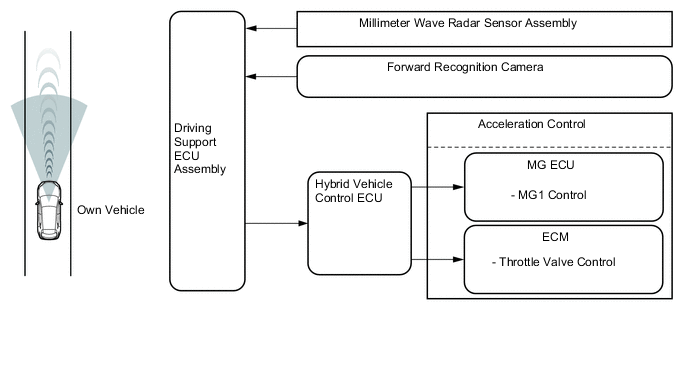
Constant Speed Control
-
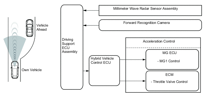
The millimeter wave radar sensor assembly and forward recognition camera transmits the information about the vehicle ahead to the driving support ECU assembly and also transmits a millimeter wave radar sensor assembly operation signal to the hybrid vehicle control ECU via the driving support ECU assembly. The hybrid vehicle control ECU compares the set vehicle speed and the actual vehicle speed, and performs constant speed control by regulating the throttle in order to attain the set vehicle speed.
-
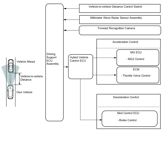
In vehicle-to-vehicle distance control mode, the driving support ECU assembly performs deceleration control, follow-up control or acceleration control based on the information about the vehicle ahead transmitted from the millimeter wave radar sensor assembly and forward recognition camera.
-
-
Vehicle-to-vehicle Distance Control Mode
-
In vehicle-to-vehicle distance control mode, the hybrid vehicle control ECU performs deceleration control function, follow-up control and acceleration control function based on the information about the vehicle ahead transmitted from the driving support ECU assembly, millimeter wave radar sensor assembly and forward recognition camera.
-
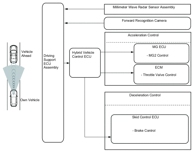
Deceleration Control
-
The driving support ECU assembly calculates the target deceleration rate in accordance with signals from the millimeter wave radar sensor assembly, forward recognition camera and transmits a deceleration request signal to the hybrid vehicle control ECU. Upon receiving this signal, the hybrid vehicle control ECU performs engine, MG2 and brake control in order to cause the vehicle to decelerate
-
This control is not performed in the presence of a parked vehicle or object, or below the settable vehicle speed range.
-
If the driving support ECU assembly determines that further deceleration is necessary, it transmits a brake request signal to the skid control ECU. Upon receiving this signal, the skid control ECU then activates the brake actuator to apply the brakes.
-
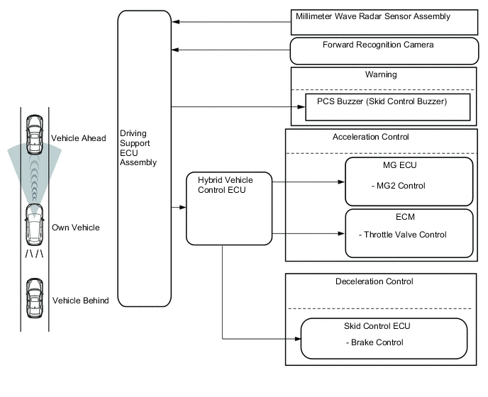
At this time, if the deceleration rate is higher than a predetermined value, the skid control ECU outputs a stop light illumination request signal to the stop light control relay in order to inform anyone who might be following the vehicle.
-
If the vehicle is not decelerating adequately, the skid control ECU sounds the PCS buzzer (skid control buzzer assembly) based on a request signal from the driving support ECU assembly. The buzzer is sounded to urge the driver to depress the brake pedal.
-
-
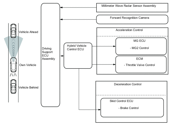
Follow-up Control
-
After performing deceleration control, the driving support ECU assembly transmits request signals to the hybrid vehicle control ECU so that the vehicle can follow the vehicle ahead while maintaining the proper vehicle-to-vehicle distance. The actual distance maintained for each distance level (long, middle and short) varies in accordance with vehicle speed. Upon receiving these signals, these ECUs control the motive force in order to perform follow-up control.
-
3 levels (long, middle, and short) of vehicle-to-vehicle distance can be selected by operating the vehicle-to-vehicle distance control switch.
-
-
Acceleration Control
-
If the driving support ECU assembly detects that either the vehicle ahead or own vehicle has changed lanes, request signal is transmitted to the hybrid vehicle control ECU in order to attain the set vehicle speed. Upon receiving this signal, the hybrid vehicle control ECU controls the motive force of the engine and MG2 in order to perform acceleration control.
-
-
Automatic Cancel Control
-
If any of the conditions listed below occur while the vehicle is being driven using cruise control, speed control by the cruise control system will be canceled. Then, the following warning items will appear for the driver.
Constant Speed Control Mode Situation Warning Multi-information Display 
Buzzer in the combination meter sub-assembly If the condition listed below occurs, the hybrid vehicle control ECU clears the set vehicle speed and cancels speed control by the cruise control system
-
An open or short circuit in the stop light switch
Speed control by the cruise control system is disabled until the conditions are corrected or the cruise control system is turned off and back on again using the ON-OFF button on the cruise control switch.
CHECK CRUISE CONTROL SYSTEM Illuminates Sounds If the condition listed below occurs, the hybrid vehicle control ECU clears the set vehicle speed and cancels speed control by the cruise control system.
-
Malfunction in the hybrid system
Speed control by the cruise control system is disabled until the conditions are remedied or the cruise control system is turned off and back on again using the ON-OFF button on the cruise control switch.
- Illuminates - If the condition listed below occurs, the hybrid vehicle control ECU clears the set vehicle speed and cancels speed control by the cruise control system.
-
The vehicle speed drops more than 16 km/h (10 mph) below the set vehicle speed.
- Does not illuminate - If the condition listed below occurs, the hybrid vehicle control ECU cancels speed control by the cruise control system while retaining the set vehicle speed in its memory.
-
The vehicle speed drops below low speed limit (approximately 40 km/h [25 mph]).
- Does not illuminate - If either of the conditions listed below occurs, the hybrid vehicle control ECU cancels speed control by the cruise control system.
-
VSC operates during cruise control driving.
-
TRC operates for a certain period of time during cruise control driving.
- Does not illuminate - Vehicle-to-vehicle Distance Control Mode Situation Warning Multi-information Display Buzzer in the combination meter sub-assembly If the condition listed below occurs, the hybrid vehicle control ECU clears the set vehicle speed and cancels speed control by the cruise control system.
-
Stop light switch open or short circuit.
Speed control by the cruise control system is disabled until the conditions are corrected or the cruise control system is turned off and back on again using the ON-OFF button on the cruise control switch.
CHECK CRUISE CONTROL SYSTEM Illuminates Sounds If any of the conditions listed below occur, the hybrid vehicle control ECU clears the set vehicle speed and cancels speed control by the cruise control system.
-
Malfunction of the millimeter wave radar sensor assembly.
-
Misalignment of the axis of the millimeter wave radar sensor assembly.
-
Malfunction in the dynamic radar cruise control system other than those given above.
Speed control by the cruise control system is disabled until the power switch is turned on (IG) again.
CHECK CRUISE CONTROL SYSTEM Illuminates Sounds If the condition listed below occurs, the hybrid vehicle control ECU clears the set vehicle speed and cancels speed control by the cruise control system.
-
Malfunction in the hybrid system.
Speed control by the cruise control system is disabled until the condition is corrected or the cruise control system is turned off and back on again using the ON-OFF button on the cruise control switch.
- Illuminates - If the condition listed below occurs, the hybrid vehicle control ECU cancels speed control by the cruise control system while retaining the set vehicle speed in its memory.
-
The millimeter wave radar sensor assembly or the emblem are dirty.
Speed control by the cruise control system is prohibited until the condition is corrected or the cruise control system is turned off and back on again using the ON-OFF button on the cruise control switch.
CLEAN RADAR SENSOR Illuminates Sounds If either of the conditions listed below occurs, the hybrid vehicle control ECU cancels speed control by the cruise control system while retaining the set vehicle speed in its memory.
-
The measurement becomes extremely unstable due to poor weather conditions.
-
Brake control by the dynamic radar cruise control system is temporarily unavailable.
-
Misalignment of the axis of the millimeter wave radar sensor assembly.
-
A Malfunction in the forward recognition camera.
-
Forward recognition camera temporarily not available.
Speed control by the cruise control system is prohibited until the condition is corrected or the cruise control system is turned off and back on again using the ON-OFF button on the cruise control switch.
CRUISE CONTROL NOT AVAILABLE Illuminates Sounds If the condition listed below occurs, the hybrid vehicle control ECU cancels speed control by the cruise control system while retaining the set vehicle speed in its memory.
-
The vehicle speed drops below the low speed limit (approximately 40 km/h [25 mph]).
- Does not illuminate Sounds Twice If either of the conditions listed below occurs, the hybrid vehicle control ECU cancels speed control by the cruise control system.
-
VSC operates during cruise control driving.
-
TRC operates for a certain period of time during cruise control driving.
- Does not illuminate - -
-
-
-
-
CONSTRUCTION
-
Cruise Control Switch
-
The cruise control switch consists of the ON-OFF button, and the +RES, -SET and CANCEL switches. The ON-OFF button, +RES, -SET and CANCEL switches are operated by moving the lever in the 4 directions indicated.
-
When the cruise control system is turned on using the main switch (ON-OFF button), the system starts in vehicle-to-vehicle distance control mode. When the main switch is pushed and held for 1.5 seconds or more from the cruise control system off, The system changes to constant control mode.
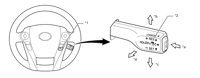
*1 Steering Pad Switch Assembly
-
Vehicle-to-vehicle Distance Control Switch
*2 Cruise Control Switch *a ON-OFF Button *b +RES Switch *c -SET Switch *d CANCEL Switch -
-
-
Vehicle-to-vehicle Distance Control Switch
-
While the vehicle is being driven in vehicle-to-vehicle distance control mode, the vehicle-to-vehicle distance setting can be changed as follows each time the distance control switch is pressed; long → middle → short → long.
-
If the power switch is turned off and back on (IG), the system will default to "long".
-
The vehicle-to-vehicle distance is as follows:
Mode Vehicle-to-vehicle Distance* Long Approximately 50 m (160 ft.) Middle Approximately 40 m (130 ft.) Short Approximately 30 m (100 ft.) Tech Tips
*: While driving at a speed of 80 km/h (50 mph).
-
-
Millimeter Wave Radar Sensor
-
The millimeter wave radar sensor assembly emits electrical waves in the millimeter waveband towards the front of the vehicle. When a preceding vehicle is present, the sensor receives electrical waves reflected off of the rear surface of the preceding vehicle. The system determines whether there is a preceding vehicle in the same lane and calculates the distance to the preceding vehicle and relative vehicle speed according to the change in frequency of the received electrical waves and using an electronic scan. This calculated data is then output to the driving support ECU assembly. For details about the millimeter wave radar sensor assembly, refer to the pre-collision system.
-
-
Forward Recognition Camera
-
The forward recognition camera captures images of the front with the monocular camera that is equipped. By performing image processing on the captured images, the size of the preceding vehicle and lane marker recognition of the road are possible; in addition, improvements were designed for things such as recognition precision for preceding vehicles, road judgment and detection of vehicles cutting into the lane. For details about the forward recognition camera, refer to the lane departure alert system (w/ steering control).
-
-
-
OPERATION
-
Combination Meter Sub-assembly
-
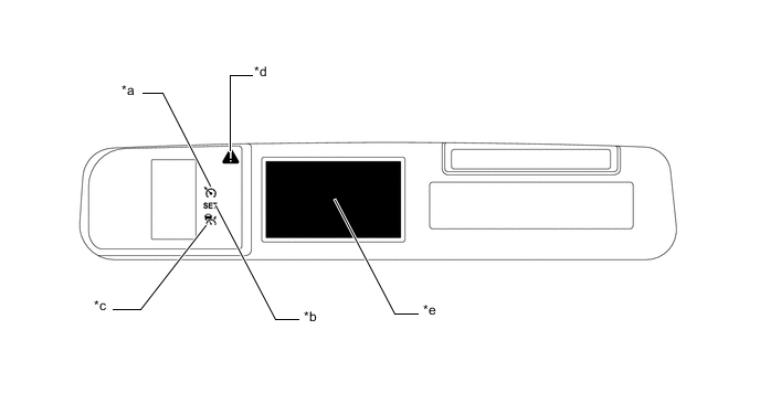
The combination meter sub-assembly has a master warning light, cruise control indicator light (constant speed control mode), cruise control indicator light (vehicle-to-vehicle distance control mode), cruise SET indicator light, buzzer, and multi-information display to provide warnings and messages regarding the dynamic radar cruise control system.
-
The multi-information display displays the set vehicle speed, vehicle ahead mark, and warning message.
Figure 1. LHD Models
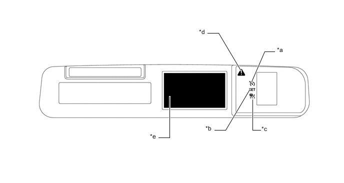
*a Cruise Control Indicator Light (Constant Speed Control Mode) *b Cruise SET Indicator Light *c Cruise Control Indicator Light (Vehicle-to-vehicle Distance Control Mode) *d Master Warning Light *e Multi-information Display - - Figure 2. RHD Models
*a Cruise Control Indicator Light (Constant Speed Control Mode) *b Cruise SET Indicator Light *c Cruise Control Indicator Light (Vehicle-to-vehicle Distance Control Mode) *d Master Warning Light *e Multi-information Display - - Constant Speed Control Mode Condition Multi-information Display*1, *2 

Buzzer Being Controlled 
Illuminates Does not illuminate - System Check CHECK CRUISE CONTROL SYSTEM Does not illuminate Illuminates Buzzer in the combination meter sub-assembly sounds *1: While driving at a set speed of 100 km/h (62 mph).
*2: These illustrations are examples.
Vehicle-to-vehicle Distance Control Mode Condition Multi-information Display*1, *2 
Buzzer Set Standby RADAR READY Illuminates Does not illuminate - Set Standby (Short) 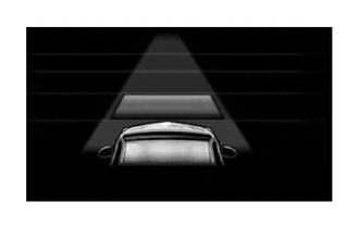
Illuminates Does not illuminate - Under Constant Speed Control (No Vehicle Ahead, Middle) 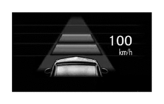
Illuminates Does not illuminate - Under Follow-up Control (Vehicle Ahead, Long 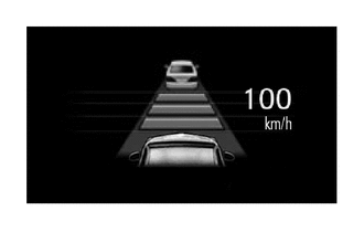
Illuminates Does not illuminate - Deceleration Control/Vehicle Approach Warning (Vehicle Ahead, Long) 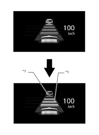
*1 Amber Illuminates Does not illuminate PCS Buzzer (Skid Control Buzzer Assembly) sounds continuously Blinks Millimeter Wave Radar Sensor Assembly or the Emblem are Dirty. CLEAN RADAR SENSOR Does not illuminate Illuminates Buzzer in the combination meter sub-assembly sounds
-
Poor Weather Conditions
-
Brake control by the dynamic radar cruise control system is temporarily unavailable.
-
Misalignment of the axis of the millimeter wave radar sensor assembly.
-
A Malfunction in the forward recognition camera
-
Forward recognition camera temporarily not available.
CRUISE CONTROL NOT AVAILABLE Does not illuminate Illuminates Buzzer in the combination meter sub-assembly sounds System Check CHECK CRUISE CONTROL SYSTEM Does not illuminate Illuminates Buzzer in the combination meter sub-assembly sounds *1: While driving at a set speed of 100km/h (62 mph).
*2: These illustrations are examples.
-
-
-
-
DIAGNOSIS
-
If a malfunction occurs in the dynamic radar cruise control system during cruise control operation, the hybrid vehicle control ECU and driving support ECU assembly cancels the cruise control operation, illuminates the master warning light, sounds a buzzer in the combination meter sub-assembly, and displays a warning message on the multi-information display to inform the driver of the malfunction. At this time, the malfunction is stored in memory as a Diagnostic Trouble Code (DTC).
-
The DTCs can be read when a Global TechStream (GTS) is connected to the DLC3. For details, refer to the Repair Manual.
-