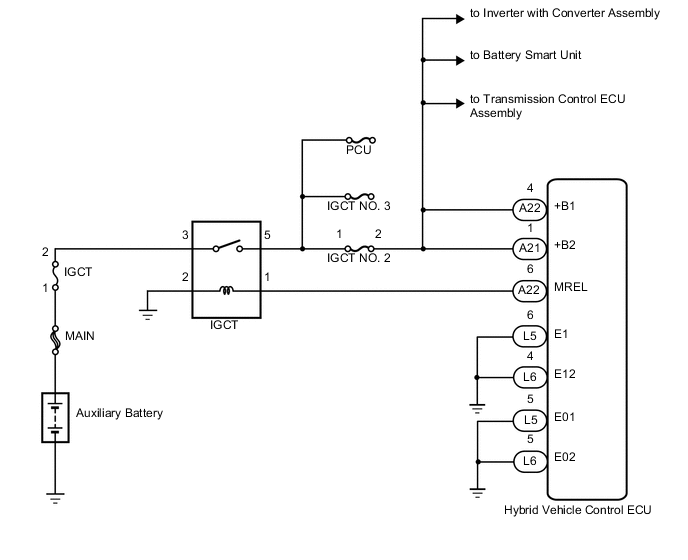
HYBRID CONTROL SYSTEM ECU Power Source Circuit
DESCRIPTION
When the power switch is turned on (IG), current flows from the MREL terminal of the hybrid vehicle control ECU to the IGCT relay. This closes the IGCT relay contact points and supplies power to the +B1 and +B2 terminals of the hybrid vehicle control ECU.
WIRING DIAGRAM
PROCEDURE
-
CHECK HYBRID VEHICLE CONTROL ECU (+B1, +B2 VOLTAGE)
-
Turn the power switch on (IG).
-
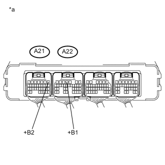
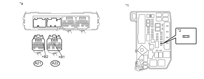
Text in Illustration *a Component with harness connected
(Hybrid Vehicle Control ECU)
Measure the voltage according to the value(s) in the table below.
Standard Voltage Tester Connection Condition Specified Condition A22-4 (+B1) - Body ground Power switch on (IG) 11 to 14 V A21-1 (+B2) - Body ground Power switch on (IG) 11 to 14 V -
Turn the power switch off.
NG 
CHECK HYBRID VEHICLE CONTROL ECU (MREL VOLTAGE) Click here
OK 
-
-
CHECK HARNESS AND CONNECTOR (HYBRID VEHICLE CONTROL ECU - BODY GROUND)
-
Disconnect the L5 and L6 hybrid vehicle control ECU connectors.
-
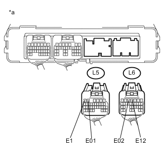
Text in Illustration *a Rear view of wire harness connector
(to Hybrid Vehicle Control ECU)
Measure the resistance according to the value(s) in the table below.
Standard Resistance Tester Connection Condition Specified Condition L5-5 (E01) - Body ground Always Below 1 Ω L5-6 (E1) - Body ground Always Below 1 Ω L6-4 (E12) - Body ground Always Below 1 Ω L6-5 (E02) - Body ground Always Below 1 Ω -
Reconnect the L5 and L6 hybrid vehicle control ECU connectors.
OK 
GO TO PROBLEM SYMPTOMS TABLE Click here
NG
REPAIR OR REPLACE HARNESS OR CONNECTOR
-
-
CHECK HYBRID VEHICLE CONTROL ECU (MREL VOLTAGE)
-
Turn the power switch on (IG).
-
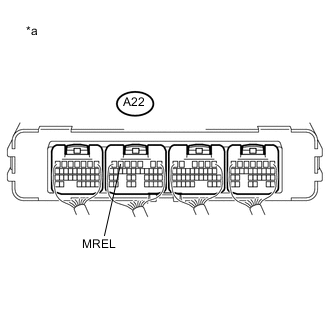
Text in Illustration *a Component with harness connected
(Hybrid Vehicle Control ECU)
Measure the voltage according to the value(s) in the table below.
Standard Voltage Tester Connection Condition Specified Condition A22-6 (MREL) - Body ground Power switch on (IG) 11 to 14 V -
Turn the power switch off.
NG
REPLACE HYBRID VEHICLE CONTROL ECU Click here
OK
-
-
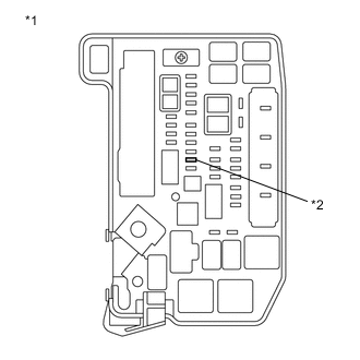
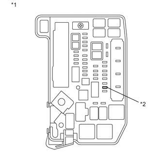
CHECK FUSE (IGCT NO. 2)
-
Remove the IGCT NO. 2 fuse from the engine room relay block and junction block assembly.
-
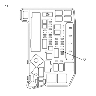
Text in Illustration *1 Engine Room Relay Block and Junction Block Assembly *2 IGCT NO. 2 Fuse Measure the resistance according to the value(s) in the table below.
Standard Resistance Tester Connection Condition Specified Condition IGCT NO. 2 fuse terminals Always Below 1 Ω -
Install the IGCT NO. 2 fuse.
NG
CHECK HARNESS AND CONNECTOR (HYBRID VEHICLE CONTROL ECU - ENGINE ROOM RELAY BLOCK AND JUNCTION BLOCK ASSEMBLY) Click here
OK
-
-
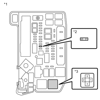
CHECK FUSE (IGCT)
-
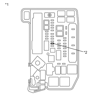
Text in Illustration *1 Engine Room Relay Block and Junction Block Assembly *2 IGCT Fuse Remove the IGCT fuse from the engine room relay block and junction block assembly.
-
Measure the resistance according to the value(s) in the table below.
Standard Resistance Tester Connection Condition Specified Condition IGCT fuse terminals Always Below 1 Ω -
Install the IGCT fuse.
NG
CHECK HARNESS AND CONNECTOR (ENGINE ROOM RELAY BLOCK AND JUNCTION BLOCK ASSEMBLY (IGCT FUSE - IGCT NO. 2 FUSE)) Click here
OK
-
-
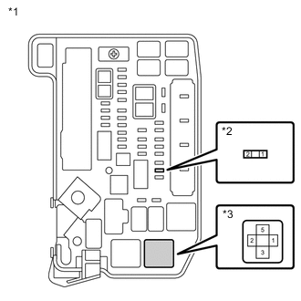
INSPECT RELAY (IGCT)
-
Remove the IGCT relay from the engine room relay block and junction block assembly.
-
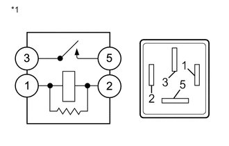
Text in Illustration *1 IGCT Relay Measure the resistance according to the value(s) in the table below.
Standard Resistance Tester Connection Condition Specified Condition 3 - 5 Auxiliary battery voltage is not applied between terminals 1 and 2 10 kΩ or higher Auxiliary battery voltage is applied between terminals 1 and 2 Below 1 Ω -
Install the IGCT relay.
NG
REPLACE RELAY (IGCT)
OK
-
-
CHECK HARNESS AND CONNECTOR (HYBRID VEHICLE CONTROL ECU - ENGINE ROOM RELAY BLOCK AND JUNCTION BLOCK ASSEMBLY)
-
Remove the IGCT relay from the engine room relay block and junction block assembly.
-
Disconnect the A21 and A22 hybrid vehicle control ECU connectors.
-
Measure the resistance according to the value(s) in the table below.
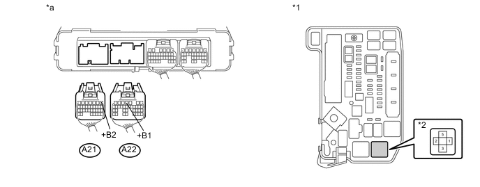
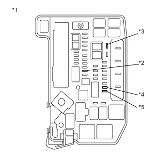
Text in Illustration *1 Engine Room Relay Block and Junction Block Assembly *2 IGCT relay *a Rear view of wire harness connector
(to Hybrid Vehicle Control ECU)
- - Standard Resistance Tester Connection Condition Specified Condition A22-4 (+B1) - 5 (IGCT relay) Always Below 1 Ω A21-1 (+B2) - 5 (IGCT relay) Always Below 1 Ω -
Install the IGCT relay.
-
Reconnect the A21 and A22 hybrid vehicle control ECU connectors.
NG
REPAIR OR REPLACE HARNESS OR CONNECTOR
OK
-
-
CHECK HARNESS AND CONNECTOR (ENGINE ROOM RELAY BLOCK AND JUNCTION BLOCK ASSEMBLY (IGCT RELAY - IGCT FUSE))
-
Text in Illustration *1 Engine Room Relay Block and Junction Block Assembly *2 IGCT Fuse Remove the IGCT fuse from the engine room relay block and junction block assembly.
-
Remove the IGCT relay from the engine room relay block and junction block assembly.
-
Text in Illustration *1 Engine Room Relay Block and Junction Block Assembly *2 IGCT Fuse *3 IGCT Relay Measure the resistance according to the value(s) in the table below.
Standard Resistance Tester Connection Condition Specified Condition 3 (IGCT relay) - 2 (IGCT fuse) Always Below 1 Ω -
Install the IGCT fuse.
-
Install the IGCT relay.
NG
REPAIR OR REPLACE HARNESS OR CONNECTOR
OK
-
-
CHECK HARNESS AND CONNECTOR (HYBRID VEHICLE CONTROL ECU - ENGINE ROOM RELAY BLOCK AND JUNCTION BLOCK ASSEMBLY)
-
Remove the IGCT relay from the engine room relay block and junction block assembly.
-
Disconnect the A22 hybrid vehicle control ECU connector.
-
Measure the resistance according to the value(s) in the table below.
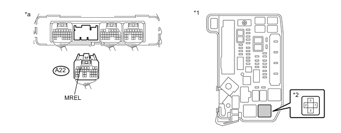
Text in Illustration *1 Engine Room Relay Block and Junction Block Assembly *2 IGCT Relay *a Rear view of wire harness connector
(to Hybrid Vehicle Control ECU)
- - Standard Resistance Tester Connection Condition Specified Condition A22-6 (MREL) - 1 (IGCT relay) Always Below 1 Ω A22-6 (MREL) or 1 (IGCT relay) - Body ground and other terminals Always 10 kΩ or higher -
Install the IGCT relay.
-
Reconnect the A22 hybrid vehicle control ECU connectors.
NG
REPAIR OR REPLACE HARNESS OR CONNECTOR
OK
-
-
CHECK HARNESS AND CONNECTOR (ENGINE ROOM RELAY BLOCK AND JUNCTION BLOCK ASSEMBLY - BODY GROUND)
-
Remove the IGCT relay from the engine room relay block and junction block assembly.
-
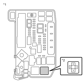
Text in Illustration *1 Engine Room Relay Block and Junction Block Assembly *2 IGCT Relay Measure the resistance according to the value(s) in the table below.
Standard Resistance Tester Connection Condition Specified Condition 2 (IGCT relay) - Body ground Always Below 1 Ω -
Install the IGCT relay.
OK
CHECK FOR INTERMITTENT PROBLEMS Click here
NG
REPAIR OR REPLACE HARNESS OR CONNECTOR
-
-
CHECK HARNESS AND CONNECTOR (HYBRID VEHICLE CONTROL ECU - ENGINE ROOM RELAY BLOCK AND JUNCTION BLOCK ASSEMBLY)
CAUTION:
Be sure to wear insulated gloves.
-
Check that the service plug grip is not installed.
Note
After removing the service plug grip, do not turn the power switch on (READY), unless instructed by the repair manual because this may cause a malfunction.
-
Disconnect the A59 inverter with converter assembly connector.
-
Disconnect the A23 transmission control ECU assembly connector.
-
Remove the No. 1 hybrid vehicle battery carrier bracket sub-assembly Click here.
-
Disconnect the L144 battery smart unit connector.
-
Text in Illustration *1 Engine Room Relay Block and Junction Block Assembly *2 IGCT No. 2 Fuse Remove the IGCT No. 2 fuse from the engine room relay block and junction block assembly.
-
Disconnect the A21 and A22 hybrid vehicle control ECU connectors.
-
Measure the resistance according to the value(s) in the table below.
Text in Illustration *1 Engine Room Relay Block and Junction Block Assembly *2 IGCT No. 2 Fuse *a Rear view of wire harness connector
(to Hybrid Vehicle Control ECU)
- - Standard Resistance Tester Connection Condition Specified Condition A22-4 (+B1) or 2 (IGCT No. 2 fuse) - Body ground and other terminals Always 10 kΩ or higher A21-1 (+B2) or 2 (IGCT No. 2 fuse) - Body ground and other terminals Always 10 kΩ or higher -
Install the IGCT No. 2 fuse.
-
Reconnect the A21 and A22 hybrid vehicle control ECU connectors.
-
Reconnect the L144 battery smart unit connector.
-
Install the No. 1 hybrid vehicle battery carrier bracket sub-assembly.
-
Reconnect the A23 transmission control ECU assembly connector.
-
Reconnect the A59 inverter with converter assembly connector.
OK
REPLACE FUSE (IGCT NO. 2)
NG
REPAIR OR REPLACE HARNESS OR CONNECTOR Click here
-
-
CHECK HARNESS AND CONNECTOR (ENGINE ROOM RELAY BLOCK AND JUNCTION BLOCK ASSEMBLY (IGCT FUSE - IGCT NO. 2 FUSE))
-
Text in Illustration *1 Engine Room Relay Block and Junction Block Assembly *2 IGCT Fuse *3 IGCT No. 3 fuse *4 IGCT No. 2 fuse *5 PCU Fuse Remove the IGCT fuse, IGCT No. 2 fuse, IGCT No. 3 fuse and PCU fuse from the engine room relay block and junction block assembly.
-
Remove the IGCT relay from the engine room relay block and junction block assembly.
-

Text in Illustration *1 Engine Room Relay Block and Junction Block Assembly *2 IGCT Fuse *3 IGCT Relay Measure the resistance according to the value(s) in the table below.
Standard Resistance Tester Connection Condition Specified Condition 3 (IGCT relay) or 2 (IGCT fuse) - Body ground and other terminals Always 10 kΩ or higher -
Text in Illustration *1 Engine Room Relay Block and Junction Block Assembly *2 IGCT No. 2 Fuse *3 IGCT Relay Measure the resistance according to the value(s) in the table below.
Standard Resistance Tester Connection Condition Specified Condition 5 (IGCT relay) or 1 (IGCT No. 2 fuse) - Body ground and other terminals Always 10 kΩ or higher -
Install the IGCT fuse, IGCT No. 2 fuse, IGCT No. 3 fuse and PCU fuse.
-
Install the IGCT relay.
OK
REPLACE FUSE (IGCT)
NG
REPAIR OR REPLACE HARNESS OR CONNECTOR Click here
-
-
REPAIR OR REPLACE HARNESS OR CONNECTOR
NEXT
REPLACE FUSE (IGCT NO. 2)
-
REPAIR OR REPLACE HARNESS OR CONNECTOR
NEXT
REPLACE FUSE (IGCT)