NAVIGATION SYSTEM(for SD), Diagnostic DTC:B1324
| DTC Code | DTC Name |
|---|---|
| B1324 | Lost Communication with Meter |
DESCRIPTION
This DTC is stored when a communication error occurs between the navigation receiver assembly and combination meter assembly.
DTC No. |
Detection Item |
DTC Detection Condition |
Trouble Area |
|---|---|---|---|
B1324 |
Lost Communication with Meter |
After the navigation receiver assembly receives a registration information signal, which is sent by the combination meter assembly when the engine switch is on (ACC), 1 or more times, the navigation receiver assembly cannot receive the signal for 30 seconds or more. |
|
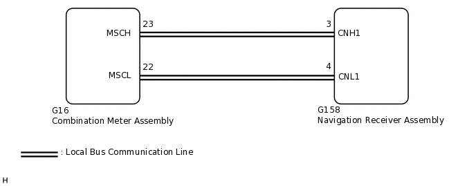
WIRING DIAGRAM
CAUTION / NOTICE / HINT
Check that the wire harness is properly installed and does not have any sharp bends, pinching or loose connections.
When replacing the combination meter assembly, make sure to replace it with a new one.
PROCEDURE
CHECK HARNESS AND CONNECTOR (NAVIGATION RECEIVER ASSEMBLY - COMBINATION METER ASSEMBLY)
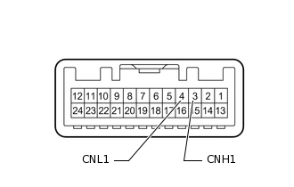
Disconnect the G158 navigation receiver assembly connector.
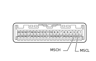
Disconnect the G16 combination meter assembly connector.
Measure the resistance according to the value(s) in the table below.
Standard Resistance
Tester Connection
Condition
Specified Condition
G158-3 (CNH1) - G16-23 (MSCH)
Always
Below 1 Ω
G158-4 (CNL1) - G16-22 (MSCL)
Always
Below 1 Ω
G158-3 (CNH1) - Body ground
Always
10 kΩ or higher
G158-4 (CNL1) - Body ground
Always
10 kΩ or higher
G158-3 (CNH1) - G158-4 (CNL1)
Always
10 kΩ or higher
Measure the voltage according to the value(s) in the table below.
Standard Voltage
Tester Connection
Condition
Specified Condition
G158-3 (CNH1) - Body ground
Always
Below 1 V
G158-4 (CNL1) - Body ground
Always
Below 1 V
Result
Proceed to
OK
NG
NG REPAIR OR REPLACE HARNESS OR CONNECTOR
INSPECT COMBINATION METER ASSEMBLY
Remove the combination meter assembly.
-
Measure the resistance according to the value(s) in the table below.
Standard Resistance
Tester Connection
Condition
Specified Condition
23 (MSCH) - 22 (MSCL)
Always
108 to 132 Ω
Result
Proceed to
OK
NG
INSPECT NAVIGATION RECEIVER ASSEMBLY
Remove the navigation receiver assembly.
-
Measure the resistance according to the value(s) in the table below.
Standard Resistance
Tester Connection
Condition
Specified Condition
3 (CNH1) - 4 (CNL1)
Always
108 to 132 Ω
Result
Proceed to
OK
NG
CHECK COMBINATION METER ASSEMBLY
Replace the combination meter assembly.
Clear the DTCs.
Body Electrical > Navigation System > Clear DTCs
Check for DTCs.
Body Electrical > Navigation System > Trouble Codes
OK
No DTCs are output.
Result
Proceed to
OK
NG
CHECK METER / GAUGE SYSTEM
Turn the engine switch on (IG) and wait 30 seconds.
Operate the steering pad switch assembly and check that the audio tab is displayed on the multi-information display in the combination meter assembly and the audio system can be operated normally.
OK
Audio system returns to normal.
Result
Proceed to
OK
NG
OK END (COMBINATION METER ASSEMBLY IS DEFECTIVE)