PARKING ASSIST MONITOR SYSTEM(w/o Side Monitor System) Guide Lines and Buttons are not Displayed for All Display Modes
| DTC Code | DTC Name |
|---|---|
| Guide Lines and Buttons are not Displayed for All Display Modes |
DESCRIPTION
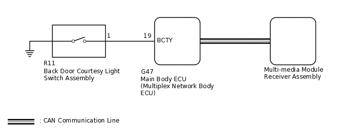
The multi-media module receiver assembly receives back door open/close signals from the main body ECU (multiplex network body ECU) via CAN communication. When the back door is open, the camera aiming cannot be adjusted correctly because the rear television camera assembly is installed on the back door. Therefore, when performing back camera position setting while the back door is open, a back door open warning message will be displayed on the screen and back camera position setting will be canceled.
Check the parking assist monitor screen display mode settings. (Check if the parking guide lines are set to off.)
WIRING DIAGRAM
CAUTION / NOTICE / HINT
When "System initialising" is displayed on the multi-media module receiver assembly after disconnecting the cable from the negative (-) battery terminal, correct the steering angle neutral point.
Depending on the parts that are replaced or operations that are performed during vehicle inspection or maintenance, calibration of other systems as well as the parking assist monitor system may be needed.
PROCEDURE
READ VALUE USING GTS
Connect the GTS to the DLC3.
Turn the engine switch on (IG).
Turn the GTS on.
Enter the following menus: Body Electrical / Main Body / Data List.
Read the Data List according to the display on the GTS.
Body Electrical > Main Body > Data List
Tester Display
Measurement Item
Range
Normal Condition
Diagnostic Note
Back Door Courtesy SW
Back door courtesy switch signal
ON or OFF
ON: Back door open
OFF: Back door closed
-
Body Electrical > Main Body > Data List
Tester Display
Back Door Courtesy SW
OK
The back door courtesy switch functions as specified in the normal condition column.
Result
Proceed to
OK
NG
INSPECT BACK DOOR COURTESY LIGHT SWITCH ASSEMBLY
Remove the back door courtesy light switch assembly.
Inspect the back door courtesy light switch assembly.
Result
Proceed to
OK
NG
CHECK HARNESS AND CONNECTOR (MAIN BODY ECU [MULTIPLEX NETWORK BODY ECU] - BACK DOOR COURTESY LIGHT SWITCH ASSEMBLY)
Disconnect the G47 main body ECU (multiplex network body ECU) connector.
Click here
Disconnect the R11 back door courtesy light switch assembly connector.
Measure the resistance according to the value(s) in the table below.
Standard Resistance
Tester Connection
Condition
Specified Condition
G47-19 (BCTY) - R11-1
Always
Below 1 Ω
G47-19 (BCTY) - Body ground
Always
10 kΩ or higher
Result
Proceed to
OK
NG
NG REPAIR OR REPLACE HARNESS OR CONNECTOR