FUEL INJECTOR REMOVAL
-
DISCHARGE FUEL SYSTEM PRESSURE
-
Check that the battery positive voltage is above 12 V.
-
Discharge the fuel system pressure Click here.
-
Disconnect the negative terminal cable from the battery.
-
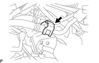
Pinch and pull the No. 1 fuel hose (fuel tube connector) to disconnect it from the fuel pressure pulsation damper assembly.
CAUTION:
-
Always read the precautions Click here before disconnecting the fuel tube connector (quick type).
-
The fuel tube may spray fuel as a result of pressure that remains in it. Do not allow fuel to be sprayed in the engine compartment.
-
-
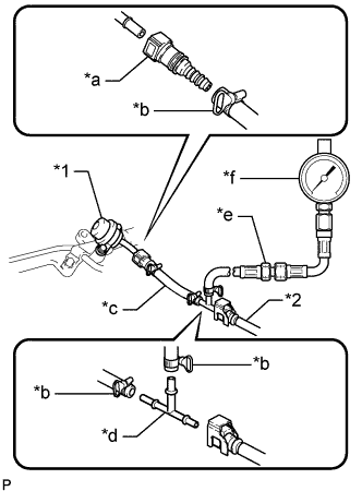
Text in Illustration *1 Fuel Pressure Pulsation Damper Assembly *2 No. 1 Fuel Hose *a SST (Fuel Tube Connector) *b SST (Hose Band) *c SST (Hose) *d SST (T-Joint) *e SST (Hose Joint) *f SST (Pressure Gauge) Install SST (pressure gauge) as shown in the illustration.
- SST
- 09268-45101 ( 09268-41250, 09268-41260, 09268-41280, 09268-41500, 09268-41700, 95336-08070 )
-
Wipe off any gasoline.
-
Reconnect the negative terminal cable.
-
Operate the fuel pump.
-
Connect the intelligent tester to the DLC3.
-
Turn the ignition switch to ON.
Note
Do not start the engine.
-
Turn the intelligent tester on.
-
Enter the following menus: Powertrain / Engine and ECT / Active Test / Control the Fuel Pump / Speed.
-
-
Measure the fuel pressure.
Standard fuel pressure 281 to 287 kPa (2.87 to 2.93 kgf/cm2, 40.8 to 41.7 psi) If the pressure is higher than the specification, replace the fuel pressure regulator assembly.
If the pressure is lower than the specification, check the fuel hoses and connections, fuel pump, fuel filter assembly and fuel pressure regulator assembly.
-
Start the engine.
-
Measure the fuel pressure.
Standard fuel pressure 281 to 287 kPa (2.87 to 2.93 kgf/cm2, 40.8 to 41.7 psi) If the pressure is not as specified, check the fuel pump, fuel pressure regulator assembly and/or fuel injector assemblies.
-
Stop the engine.
-
Check that the fuel pressure remains as specified for 5 minutes after the engine has stopped.
Standard fuel pressure 147 kPa (1.5 kgf/cm2, 21 psi) or more If the pressure is not as specified, check the fuel pump, fuel pressure regulator assembly and/or fuel injector assemblies.
-
After checking the fuel pressure, disconnect the negative terminal cable and carefully remove SST and the fuel tube connector to prevent gasoline from spraying.
-
Reconnect the No. 1 fuel hose (fuel tube connector) to the fuel pressure pulsation damper assembly.
-
-
DISCONNECT BATTERY NEGATIVE CABLE
-
DRAIN ENGINE COOLANT
CAUTION:
Do not remove the radiator reservoir cap sub-assembly while the engine and radiator are still hot. Pressurized, hot engine coolant and steam may be released and cause serious burns.
Tech Tips
Collect the engine coolant in a container and dispose of it according to local regulations.
-
Loosen the radiator drain cock plug and drain the engine coolant.
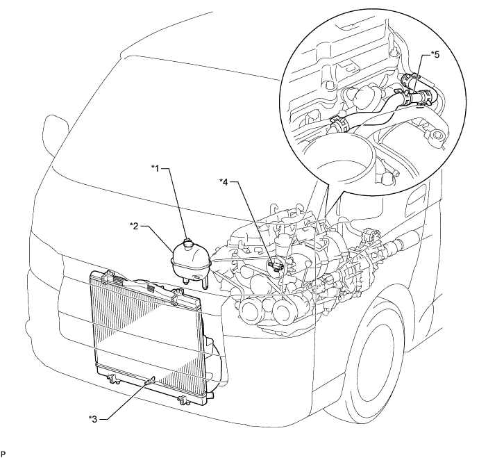
Text in Illustration *1 Radiator Reservoir Cap Sub-assembly *2 Radiator Reservoir Assembly *3 Radiator Drain Cock Plug *4 Cylinder Block Water Drain Cock Plug *5 2-Way - - -
Remove the radiator reservoir cap sub-assembly.
-
Loosen the cylinder block water drain cock plug and drain the engine coolant from the engine.
-
-
REMOVE FRONT SEAT ASSEMBLY RH (for Hi-back Seat Type)
Tech Tips
Use the same procedures described for the LH side. Click here
-
REMOVE FRONT SEAT ASSEMBLY RH (for Low-back Seat Type)
Tech Tips
Use the same procedures described for the LH side. Click here
-
REMOVE FRONT DOOR SCUFF PLATE RH
-
REMOVE ENGINE SERVICE HOLE SUB COVER SUB-ASSEMBLY
-
Roll up the carpet, and remove the 5 bolts and engine service hole sub cover.
-
-
REMOVE INTAKE AIR CONNECTOR
-
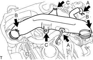
Slide the clamp and disconnect the No. 2 ventilation hose and vacuum hose. (A)
-
Loosen the 2 hose clamp bolts. (B)
-
Remove the 2 bolts and intake air connector. (C)
-
-
REMOVE THROTTLE BODY ASSEMBLY
-
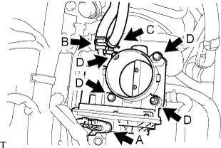
Disconnect the throttle motor connector. (A)
-
Slide the clamp and disconnect the water by-pass hose. (B)
-
Slide the clamp and disconnect the No. 2 water by-pass hose. (C)
-
for Type A:
Remove the 2 bolts and 2 nuts, and then remove the throttle body assembly. (D)
-
for Type B:
Remove the 4 bolts and throttle body assembly. (D)
-
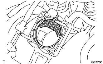
Remove the gasket from the intake manifold.
-
-
DISCONNECT FUEL HOSE
-
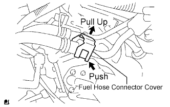
Pull the fuel hose connector cover up to release the lock. Click here
-
Disengage the fuel connector to disconnect the fuel hose. Click here
-
-
REMOVE FUEL DELIVERY PIPE SUB-ASSEMBLY
Note
Be careful not to drop the injectors when removing the delivery pipe.
-
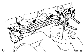
Disconnect the fuel hoses.
-
Disconnect the 4 injector connectors.
-
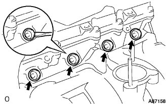
Remove the 2 bolts O-ring and fuel pulsation damper assembly.
-
Remove the 2 bolts and delivery pipe together with the 4 injectors.
-
Remove the delivery pipe spacers.
-
Using a screwdriver, pry out the 4 spacers from the cylinder head.
-
-
REMOVE INJECTOR ASSEMBLY
-
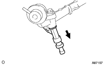
Pull out the 4 injectors from the delivery pipe.
-
Remove the O-rings from the injectors.
-