AIR CONDITIONING SYSTEM
-
CONSTRUCTION
-
An air conditioning unit that is compatible with left and right independent temperature control is used.(Models with dual zone automatic air conditioning system)
-
An inside-and-outside dual air layer type air conditioning unit is used. This type of air conditioning unit introduces outside air to the upper side and circulates inside air to the lower side, thus achieving anti-fogging performance and ventilation loss reduction.
-
A Beneficial Refrigerant Stream (BRS) type evaporator is used.
-
A Straight Flow Aluminum-II (SFA-II) heater core that is compact and offers advanced performance is used.
-
A compact wide-angle high flow defroster that gives the defroster nozzle assembly inner wall a radial shape is used to ensure superior defroster performance.
Figure 1. Air Conditioning Unit Layout Parts Location (LHD Models)
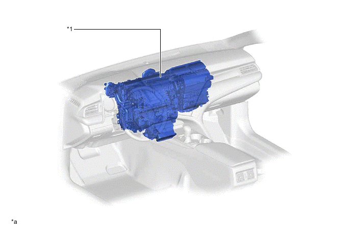
*1 Air Conditioning Unit Assembly - - *a The illustration shown is an example only. - - Figure 2. Air Conditioning Unit Layout Parts Location (RHD Models)
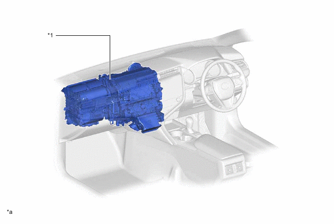
*1 Air Conditioning Unit Assembly - - *a The illustration shown is an example only. - - Figure 3. Duct Layout Parts Location (LHD Models)
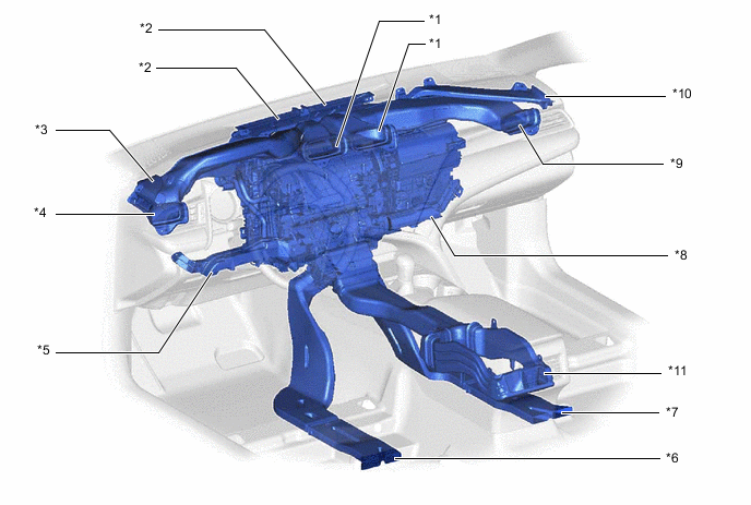
*1 Center Register Duct *2 Front Defroster Duct *3 Driver Side Defroster Duct *4 Driver Side Register Duct *5 Driver Side Footwell Register Duct *6 Driver Side Rear Footwell Register Duct *7 Passenger Side Rear Footwell Register Duct *8 Front Passenger Side Footwell Register Duct *9 Front Passenger Side Register Duct *10 Front Passenger Side Defroster Duct *11 Rear Center Register Duct - - Figure 4. Duct Layout Parts Location (RHD Models)
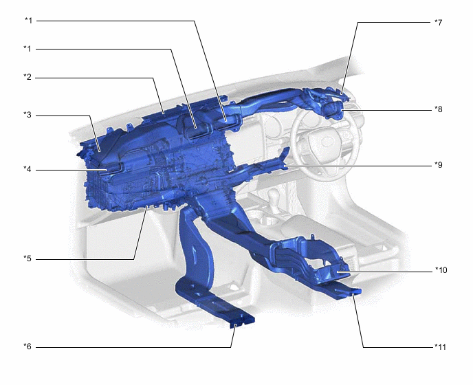
*1 Center Register Duct *2 Front Defroster Duct *3 Front Passenger Side Defroster Duct *4 Front Passenger Side Register Duct *5 Front Passenger Side Footwell Register Duct *6 Passenger Side Rear Footwell Register Duct *7 Driver Side Defroster Duct *8 Driver Side Register Duct *9 Driver Side Footwell Register Duct *10 Rear Center Register Duct *11 Driver Side Rear Footwell Register Duct - -
-
-
OPERATION
-
Mode Position and Damper Operation
Figure 5. Models with Dual Air Layer Type Air Conditioning Unit
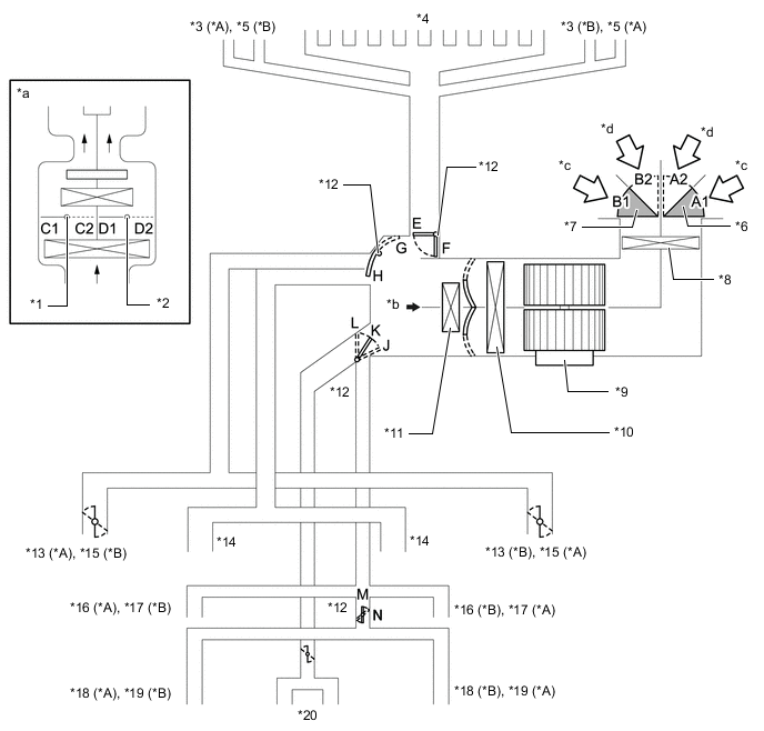
*A LHD Models *B RHD Models *1 Driver Side Air Mix Control Damper *2 Front Passenger Side Air Mix Control Damper *3 Driver Side Defroster *4 Front Defroster *5 Front Passenger Side Defroster *6 Air Inlet Control Damper (Lower Side) *7 Air Inlet Control Damper (Upper Side) *8 Clean Air Filter *9 Blower with Fan Motor Sub-assembly *10 No. 1 Cooler Evaporator Sub-assembly *11 Heater Radiator Unit Sub-assembly *12 Mode Switching Damper *13 Driver Side Register *14 Center Register *15 Front Passenger Side Register *16 Driver Side Footwell Register *17 Front Passenger Side Footwell Register *18 Driver Side Rear Footwell Register *19 Passenger Side Rear Footwell Register *20 Rear Center Register *a View from *b *b Direction of View *c Recirculated Air *d Fresh Air Functions of Main Dampers Control Damper Operation Position Damper Position Operation Air Inlet Control Damper FRESH A1, B1 Allows fresh air to enter. RECIRCULATION A2, B2 Causes internal air to recirculate. Air Mix Control Damper - C1 - C2 Varies the front passenger side mixture ratio of the fresh air and the recirculation air in order to regulate the temperature continuously from HI to LO. D2 - D1 Varies the driver side mixture ratio of the fresh air and the recirculation air in order to regulate the temperature continuously from HI to LO. Air Outlet Control Damper DEF

F, H, L, N Defrosts the windshield through the center defroster, side defrosters and side registers. FOOT/DEF

F, H, L, M to N Defrosts the windshield through the center defroster and side defrosters, while air is also blown out from the front and rear footwell register ducts. In addition, air blows out slightly from the side registers and rear center register. FOOT

F, H, K, M to N Air blows out of the front and rear footwell register ducts. In addition, air blows out slightly from the center defroster, side defrosters, side registers and rear center register. B/L

E, G, K, M to N Air blows out of the center registers, side registers, rear center register and front and rear footwell register ducts. FACE

E, G, J, M to N Air blows out of the center registers, side registers and rear center register. Figure 6. Models with Single Air Layer Type Air Conditioning Unit
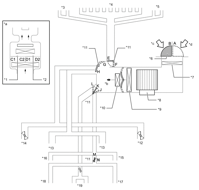
*1 Driver Side Air Mix Control Damper *2 Front Passenger Side Air Mix Control Damper *3 Front Passenger Side Defroster *4 Front Defroster *5 Driver Side Defroster *6 Air Inlet Control Damper *7 Clean Air Filter *8 Blower with Fan Motor Sub-assembly *9 No. 1 Cooler Evaporator Sub-assembly *10 Heater Radiator Unit Sub-assembly *11 Mode Switching Damper *12 Driver Side Register *13 Center Register *14 Front Passenger Side Register *15 Driver Side Footwell Register *16 Front Passenger Side Footwell Register *17 Driver Side Rear Footwell Register *18 Passenger Side Rear Footwell Register *19 Rear Center Register - - *a View from *b *b Direction of View *c Recirculated Air *d Fresh Air Functions of Main Dampers Control Damper Operation Position Damper Position Operation Air Inlet Control Damper FRESH A Allows fresh air to enter. RECIRCULATION B Causes internal air to recirculate. Air Mix Control Damper - C1 - C2 Varies the front passenger side mixture ratio of the fresh air and the recirculation air in order to regulate the temperature continuously from HI to LO. D2 - D1 Varies the driver side mixture ratio of the fresh air and the recirculation air in order to regulate the temperature continuously from HI to LO. Air Outlet Control Damper DEF
F, H, L, N Defrosts the windshield through the center defroster, side defrosters and side registers. FOOT/DEF
F, H, L, M to N Defrosts the windshield through the center defroster and side defrosters, while air is also blown out from the front and rear footwell register ducts. In addition, air blows out slightly from the side registers and rear center register. FOOT
F, H, K, M to N Air blows out of the front and rear footwell register ducts. In addition, air blows out slightly from the center defroster, side defrosters, side registers and rear center register. B/L
E, G, K, M to N Air blows out of the center registers, side registers, rear center register and front and rear footwell register ducts. FACE
E, G, J, M to N Air blows out of the center registers, side registers and rear center register. -
Air Outlets and Airflow Volume
Figure 7. LHD Models
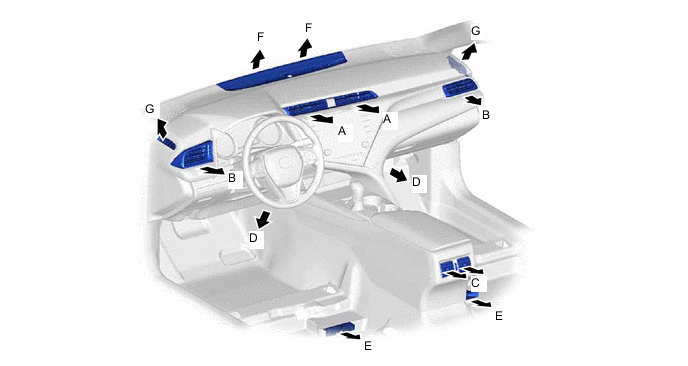
Figure 8. RHD Models
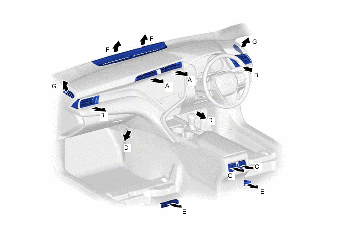
Mode FACE FOOT DEF Center Side Rear Front Rear Center Side A B C D E F G FACE


B/L

FOOT

FOOT/DEF
DEF
Tech Tips
The size of the circle ○ indicates the proportion of airflow volume.
-