POWER DOOR LOCK CONTROL SYSTEM Collision Door Lock Release Function does not Operate
DESCRIPTION
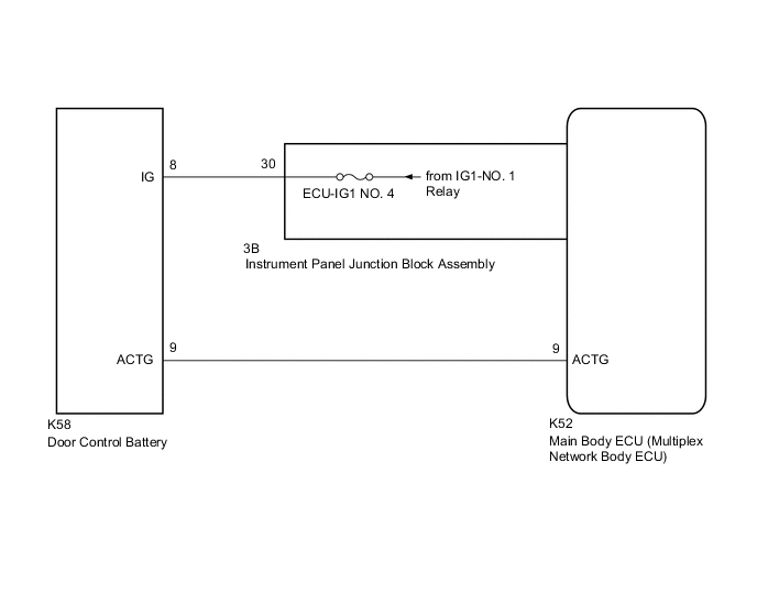
When an impact is detected, a relay inside the door control battery is operated to switch the power source of the door lock with motor assemblies from the vehicle battery to the door control battery.
WIRING DIAGRAM
CAUTION / NOTICE / HINT
Note
-
Inspect the fuses for circuits related to this system before performing the following procedure.
-
Before replacing the main body ECU (multiplex network body ECU), refer to Service Bulletin.
-
Before performing the inspection, check that DTC B1243 is not output.
PROCEDURE
-
CHECK DOOR LOCK OPERATION
-
Check door lock operation.
OK All doors lock and unlock normally. Result Proceed to OK NG
NG 
GO TO PROBLEM SYMPTOMS TABLE Click here
OK 
-
-
CHECK HARNESS AND CONNECTOR (DOOR CONTROL BATTERY - MAIN BODY ECU (MULTIPLEX NETWORK BODY ECU))
-
Disconnect the K58 door control battery connector.
-
Disconnect the K52 main body ECU (multiplex network body ECU) connector.
-
Measure the resistance according to the value(s) in the table below.
Standard Resistance Tester Connection Condition Specified Condition K58-9 (ACTG) - K52-9 (ACTG) Always Below 1 Ω K58-9 (ACTG) or K52-9 (ACTG) - Other terminals and body ground Always 10 kΩ or higher Result Proceed to OK NG
NG
REPAIR OR REPLACE HARNESS OR CONNECTOR
OK
-
-
CHECK HARNESS AND CONNECTOR (DOOR CONTROL BATTERY - INSTRUMENT PANEL JUNCTION BLOCK ASSEMBLY)
-
Disconnect the 3B instrument panel junction block assembly connector.
-
Measure the resistance according to the value(s) in the table below.
Standard Resistance Tester Connection Condition Specified Condition K58-8 (IG) - 3B-30 Always Below 1 Ω K58-8 (IG) or 3B-30 - Other terminals and body ground Always 10 kΩ or higher Result Proceed to OK NG
NG
REPAIR OR REPLACE HARNESS OR CONNECTOR
OK
-
-
CHECK HARNESS AND CONNECTOR (IG1-NO. 1 RELAY POWER SOURCE)
-
Reconnect the 3B instrument panel junction block assembly connector.
-
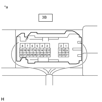
*a Component with harness connected
(Instrument Panel Junction Block Assembly)
Measure the voltage according to the value(s) in the table below.
Standard Voltage Tester Connection Condition Specified Condition 3B-30 - Body ground Ignition switch ON 11 to 14 V Result Proceed to OK NG
NG
GO TO LIGHTING SYSTEM (IG Signal Circuit) Click here
OK
-
-
REPLACE DOOR CONTROL BATTERY
-
Replace the door control battery.
Result Proceed to NEXT
NEXT
-
-
CHECK DOOR CONTROL BATTERY
-
Check door control battery operation.
OK Collision detection door lock function operates normally. Result Proceed to OK NG
OK
END (DOOR CONTROL BATTERY WAS DEFECTIVE)
NG
REPLACE MAIN BODY ECU (MULTIPLEX NETWORK BODY ECU) Click here
-