ECD SYSTEM(for Swirl Control Valve), Diagnostic DTC:P0262,P0265,P0268 and P0271
| DTC Code | DTC Name |
|---|---|
| P0262 | Cylinder 1 Injector "A" Circuit High |
| P0265 | Cylinder 2 Injector "A" Circuit High |
| P0268 | Cylinder 3 Injector "A" Circuit High |
| P0271 | Cylinder 4 Injector "A" Circuit High |
DESCRIPTION
The injector assemblies are installed in the cylinder head and inject fuel into the cylinders based on the signals from the ECM.
Injector driver is built into the ECM.
For more information on the injector assembly and fuel injection control, refer to System Description (Click here).
DTC No. |
DTC Detection Condition |
Trouble Area |
|---|---|---|
P0262 |
Short circuit of the power stage low-side (cylinder No. 1). (3 trip detection logic) |
|
DTC No. |
DTC Detection Condition |
Trouble Area |
|---|---|---|
P0265 |
Short circuit of the power stage low-side (cylinder No. 2). (3 trip detection logic) |
|
DTC No. |
DTC Detection Condition |
Trouble Area |
|---|---|---|
P0268 |
Short circuit of the power stage low-side (cylinder No. 3). (3 trip detection logic) |
|
DTC No. |
DTC Detection Condition |
Trouble Area |
|---|---|---|
P0271 |
Short circuit of the power stage low-side (cylinder No. 4). (3 trip detection logic) |
|
If DTC P0262, P0265, P0268 and/or P0271 is stored, the following symptoms may appear:
-
Engine stall
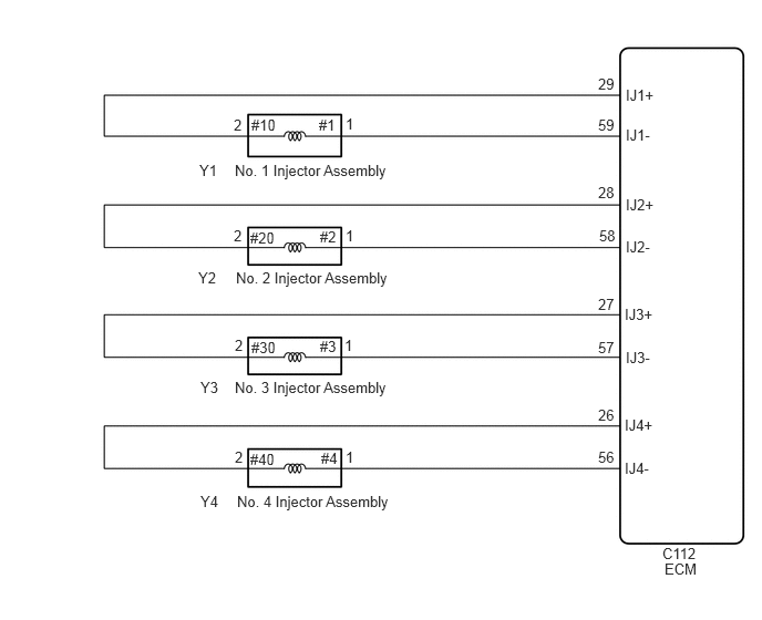
WIRING DIAGRAM
CAUTION / NOTICE / HINT
When replacing the ECM and/or injector assembly, the ECM needs Registration and Initialization (Click here).
When the ECM must be replaced, before replacing the ECM, perform the "Learning Values Save" function using the GTS. Then after installing the new ECM, perform all of the initialization/registrations for the "Learning Values Write" function by following the instructions shown on the GTS display.
Read freeze frame data using the GTS. Freeze frame data records the engine condition when malfunctions are detected. When troubleshooting, freeze frame data can help determine if the vehicle was moving or stationary, if the engine was warmed up or not, and other data from the time the malfunction occurred.
PROCEDURE
INSPECT INJECTOR ASSEMBLY
Inspect the injector assembly (Click here).
REPLACE INJECTOR ASSEMBLY OF MALFUNCTIONING CYLINDERClick here
CHECK HARNESS AND CONNECTOR (INJECTOR ASSEMBLY - ECM)
Disconnect the injector assembly connector.
Disconnect the ECM connector.
Measure the resistance according to the value(s) in the table below.
Standard Resistance
Tester Connection
Condition
Specified Condition
Y1-2 (#10) - C112-29 (IJ1+)
Always
Below 1 Ω
Y1-1 (#1) - C112-59 (IJ1-)
Always
Below 1 Ω
Y2-2 (#20) - C112-28 (IJ2+)
Always
Below 1 Ω
Y2-1 (#2) - C112-58 (IJ2-)
Always
Below 1 Ω
Y3-2 (#30) - C112-27 (IJ3+)
Always
Below 1 Ω
Y3-1 (#3) - C112-57 (IJ3-)
Always
Below 1 Ω
Y4-2 (#40) - C112-26 (IJ4+)
Always
Below 1 Ω
Y4-1 (#4) - C112-56 (IJ4-)
Always
Below 1 Ω
Y1-2 (#10) or C112-29 (IJ1+) - Body ground
Always
10 kΩ or higher
Y1-1 (#1) or C112-59 (IJ1-) - Body ground
Always
10 kΩ or higher
Y2-2 (#20) or C112-28 (IJ2+) - Body ground
Always
10 kΩ or higher
Y2-1 (#2) or C112-58 (IJ2-) - Body ground
Always
10 kΩ or higher
Y3-2 (#30) or C112-27 (IJ3+) - Body ground
Always
10 kΩ or higher
Y3-1 (#3) or C112-57 (IJ3-) - Body ground
Always
10 kΩ or higher
Y4-2 (#40) or C112-26 (IJ4+) - Body ground
Always
10 kΩ or higher
Y4-1 (#4) or C112-56 (IJ4-) - Body ground
Always
10 kΩ or higher
REPAIR OR REPLACE HARNESS OR CONNECTORClick here
REPLACE ECM
Replace the ECM (Click here).
CONFIRM WHETHER MALFUNCTION HAS BEEN SUCCESSFULLY REPAIREDClick here
REPAIR OR REPLACE HARNESS OR CONNECTOR
Repair or replace the harness or connector.
CONFIRM WHETHER MALFUNCTION HAS BEEN SUCCESSFULLY REPAIREDClick here
REPLACE INJECTOR ASSEMBLY OF MALFUNCTIONING CYLINDER
Replace the injector assembly of malfunctioning cylinder (Click here).
PERFORM REGISTRATION
Register the injector assembly compensation code (Click here).
CONFIRM WHETHER MALFUNCTION HAS BEEN SUCCESSFULLY REPAIRED
Connect the GTS to the DLC3.
Turn the ignition switch to ON and turn the GTS on.
Clear the DTCs (Click here).
Turn the ignition switch off and wait for 60 seconds or more [A].
Perform road test [B].
Repeat [A] and [B] for the number of trips detected.
Enter the following menus: Powertrain / Engine and ECT / Trouble Codes.
Confirm that the DTC is not output again.
END