ENGINE UNIT DISASSEMBLY

PROCEDURE
-
REMOVE OIL FILLER CAP SUB-ASSEMBLY
-
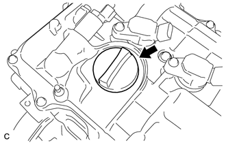
Remove the oil filler cap.
-
-
REMOVE OIL FILLER CAP GASKET
-
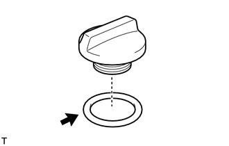
Remove the oil filler cap gasket.
-
-
REMOVE ENGINE COVER JOINT BOLT
-
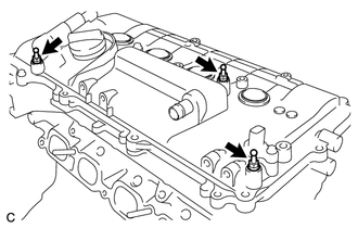
Remove the 3 engine cover joint bolts.
-
-
REMOVE WIRING HARNESS CLAMP BRACKET
-
Remove the bolt and wiring harness clamp bracket.
-
-
REMOVE SPARK PLUG
-
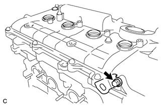
REMOVE CAMSHAFT POSITION SENSOR
-
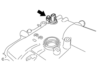
Remove the bolt and camshaft position sensor.
-
-
REMOVE CAMSHAFT TIMING OIL CONTROL VALVE ASSEMBLY
-
Remove the bolt and camshaft timing oil control valve.
-
Remove the O-ring from the camshaft timing oil control valve.
-
-
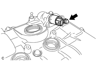
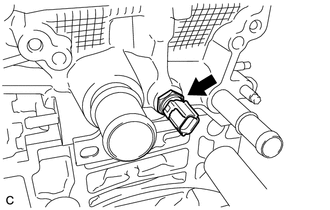
REMOVE CRANKSHAFT POSITION SENSOR
-
Remove the bolt and crankshaft position sensor.
-
-
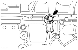
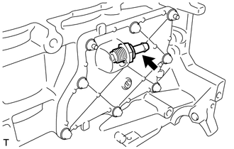
REMOVE ENGINE OIL PRESSURE SWITCH ASSEMBLY
-
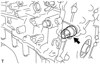
Using a 24 mm deep socket wrench, remove the engine oil pressure switch assembly.
-
-
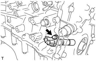
REMOVE KNOCK SENSOR
-
Remove the bolt and knock sensor.
-
-
REMOVE ENGINE COOLANT TEMPERATURE SENSOR
-
Remove the engine coolant temperature sensor and gasket.
-
-
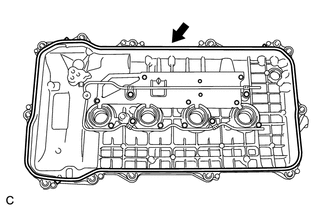
REMOVE CYLINDER HEAD COVER SUB-ASSEMBLY
-
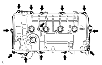
Remove the 13 bolts, seal washer and cylinder head cover.
Note
As the gaskets may stick to the cylinder head cover, be careful not to drop any of the gaskets into the engine when removing the cylinder head cover.
-
Remove the 2 gaskets from the camshaft bearing cap.
-
-
REMOVE CYLINDER HEAD COVER GASKET
-
Remove the cylinder head cover gasket.
-
-
REMOVE SPARK PLUG TUBE GASKET
-
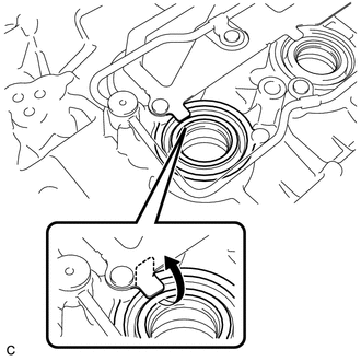
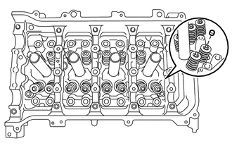
Pry up the 4 claws of the ventilation baffle plate.
Note
Do not deform the claws of the ventilation baffle plate more than necessary.
-
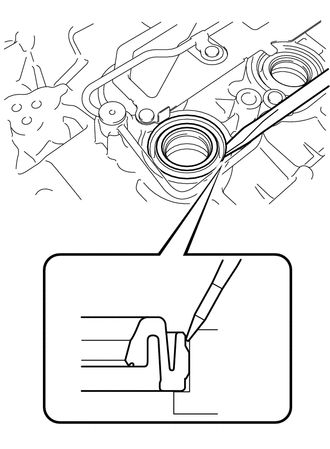
Using a screwdriver as shown in the illustration, deform each spark plug tube gasket inwards and remove the 4 spark plug tube gaskets from the cylinder head cover sub-assembly.
Note
-
As much as possible prevent the spark plug tube gaskets from being deformed. The removed spark plug tube gaskets will be used when reinstalling the new spark plug tube gaskets.
-
Do not damage the cylinder head cover subassembly.
-
Make sure not to damage the spark plug tube gasket and cylinder head cover subassembly when inserting the screwdriver in the joint area.
Tech Tips
If the cylinder head cover sub-assembly is damaged, smooth the surface with 400-grit sandpaper.
-
-
-
REMOVE OIL FILTER
-
REMOVE WATER INLET SUB-ASSEMBLY
-
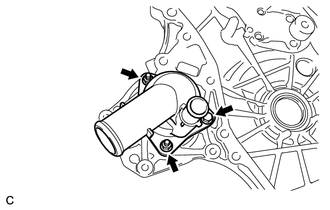
Type A:
-
Remove the bolt, 2 nuts, water inlet sub-assembly and gasket.
-
-
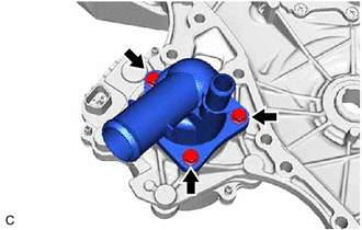
Type B:
-
Remove the 3 bolts, water inlet sub-assembly and gasket.
-
-
-
REMOVE WATER INLET SUB-ASSEMBLY STUD BOLT
-
Using an E5 "TORX" socket wrench, remove the 2 stud bolts.
Note
If a stud bolt is deformed or its threads are damaged, replace it.
-
-
SET NO. 1 CYLINDER TO TDC/COMPRESSION
-
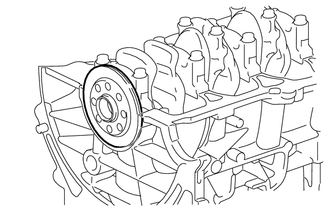
REMOVE CRANKSHAFT PULLEY
-
REMOVE NO. 1 CHAIN TENSIONER ASSEMBLY
-
REMOVE TIMING CHAIN COVER SUB-ASSEMBLY
-
Using a 8mm deep socket wrench, remove the stud bolt from the engine mounting bracket RH.
-
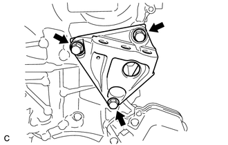
Remove the 3 bolts and engine mounting bracket RH.
-
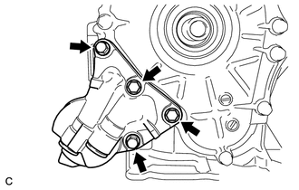
Remove the 4 bolts and oil filter bracket.
-
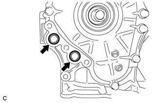
Remove the 2 O-rings.
-
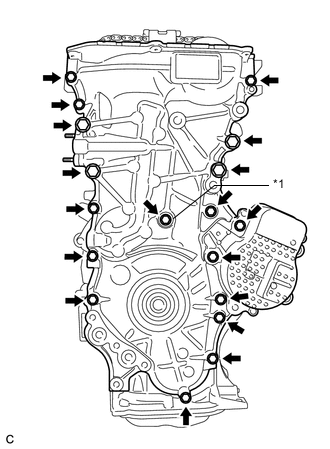
Text in Illustration *1 Gasket Remove the 18 bolts and gasket.
-
Remove the timing chain cover by prying between the timing chain cover and cylinder head or cylinder block with a screwdriver.
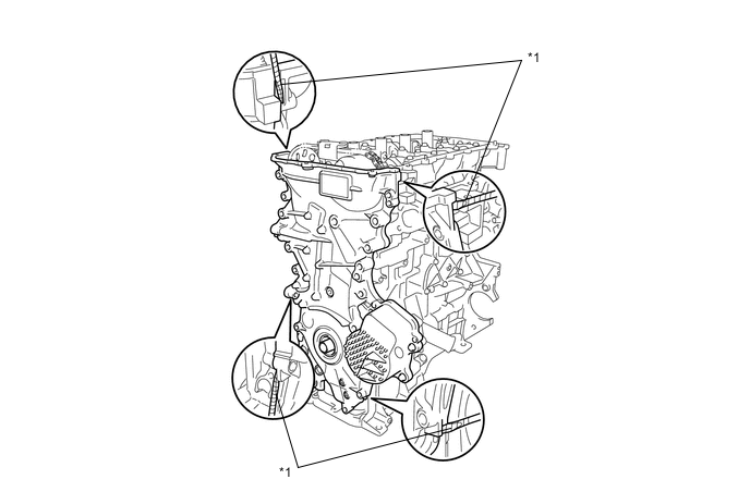
Text in Illustration *1 Protective Tape Note
-
Be careful not to damage the contact surfaces of the timing chain cover, cylinder block, and cylinder head.
-
Pry the timing chain cover out evenly in order to prevent damaging the knock pins.
Tech Tips
Tape the screwdriver tip before use.
-
-
Remove the 3 O-rings.
-
Place the timing chain cover on wooden blocks.
-
-
REMOVE TIMING CHAIN COVER OIL SEAL
-
Place the timing chain cover on wooden blocks.
-
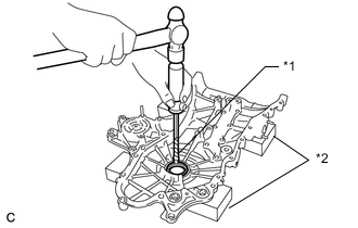
Text in Illustration *1 Protective Tape *2 Wooden Block Using a screwdriver and hammer, knock out the oil seal.
Tech Tips
Tape the screwdriver tip before use.
Note
Do not damage the surface of the oil seal press fit hole.
-
-
REMOVE CHAIN TENSIONER SLIPPER
-
REMOVE NO. 1 CHAIN VIBRATION DAMPER
-
REMOVE NO. 2 CHAIN VIBRATION DAMPER
-
REMOVE CHAIN SUB-ASSEMBLY
-
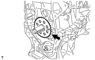
REMOVE CRANKSHAFT TIMING SPROCKET
-
REMOVE NO. 2 CHAIN SUB-ASSEMBLY
-
REMOVE NO. 1 CRANKSHAFT POSITION SENSOR PLATE
-
Remove the crankshaft position sensor plate.
-
-
REMOVE CRANKSHAFT TIMING GEAR KEY
-
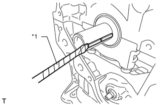
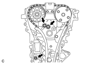
Text in Illustration *1 Protective Tape Using a screwdriver, remove the 2 crankshaft timing gear keys.
Tech Tips
Tape the screwdriver tip before use.
-
-
INSPECT CAMSHAFT TIMING GEAR ASSEMBLY
-
REMOVE CAMSHAFT TIMING GEAR ASSEMBLY
-
REMOVE CAMSHAFT TIMING SPROCKET
-
REMOVE CAMSHAFT BEARING CAP
-
REMOVE CAMSHAFT
-
REMOVE NO. 2 CAMSHAFT
-
REMOVE CAMSHAFT HOUSING STRAIGHT PIN
Note
It is not necessary to remove a straight pin unless it is being replaced.
-
REMOVE NO. 1 VALVE ROCKER ARM SUB-ASSEMBLY
-
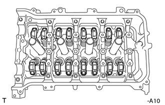
Remove the 16 valve rocker arms.
Tech Tips
Arrange the removed parts in the correct order.
-
-
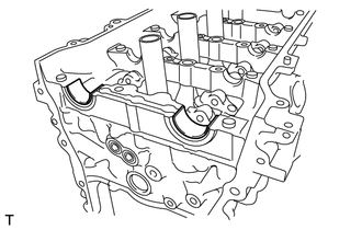
REMOVE VALVE LASH ADJUSTER ASSEMBLY
-
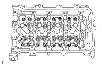
Remove the 16 valve lash adjusters from the cylinder head.
Tech Tips
Arrange the removed parts in the correct order.
-
-
REMOVE VALVE STEM CAP
-
Remove the 16 valve stem caps.
Tech Tips
Arrange the removed parts in the correct order.
-
-
REMOVE OIL CONTROL VALVE FILTER
-
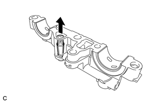
Remove the oil control valve filter from the No. 1 camshaft bearing cap.
-
-
REMOVE NO. 1 CAMSHAFT BEARING
-
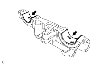
Remove the 2 camshaft bearings.
-
-
REMOVE NO. 2 CAMSHAFT BEARING
-
Remove the 2 camshaft bearings.
-
-
REMOVE CAMSHAFT HOUSING SUB-ASSEMBLY
-
REMOVE CYLINDER HEAD SUB-ASSEMBLY
-
REMOVE CYLINDER HEAD GASKET
-
REMOVE VENTILATION VALVE SUB-ASSEMBLY
-
Remove the ventilation valve sub-assembly.
-
-
REMOVE OIL PAN DRAIN PLUG
-
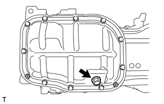
Remove the drain plug and gasket.
-
-
REMOVE NO. 2 OIL PAN SUB-ASSEMBLY
-
REMOVE OIL PUMP ASSEMBLY
-
REMOVE STIFFENING CRANKCASE ASSEMBLY
-
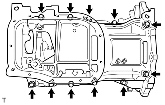
Uniformly loosen and remove the 11 bolts.
-
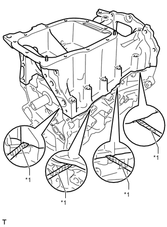
Text in Illustration *1 Protective Tape Using a screwdriver, remove the stiffening crankcase by prying between the stiffening crankcase and cylinder block.
Tech Tips
Tape the screwdriver tip before use.
Note
Be careful not to damage the contact surfaces of the crankcase and cylinder block.
-
-
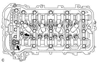
REMOVE NO. 1 TAPER SCREW PLUG
-
Type A:
-
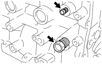
Remove the 2 No. 1 taper screw plugs.
-
-
Type B:
-
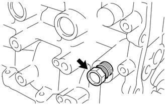
Remove the No. 1 taper screw plug.
-
-
-
REMOVE STIFFENING CRANKCASE STUD BOLT
-
Using an E5 "TORX" socket wrench, remove the 2 stud bolts.
Note
If a stud bolt is deformed or its threads are damaged, replace it.
-
-
REMOVE STIFFENING CRANKCASE RING PIN
-
Remove the 2 ring pins.
Note
It is not necessary to remove a ring pin unless it is being replaced.
-
-
REMOVE ENGINE REAR OIL SEAL
-
Remove the engine rear oil seal from the cylinder block.
-