НАГНЕТАЮЩИЙ ТОПЛИВНЫЙ НАСОС СНЯТИЕ

Note
-
When replacing the parts in the following chart (A), replace the No. 1 injection pipe sub-assembly, No. 2 injection pipe sub-assembly and/or fuel inlet pipe sub-assembly with new ones.
Replaced Parts (A) Pipes Requiring New Replacement
-
Injector assembly (including shuffling the injector assemblies between the cylinders)
-
Common rail assembly
-
Cylinder head sub-assembly
-
No. 1 injection pipe sub-assembly
-
No. 2 injection pipe sub-assembly
Supply pump assembly Fuel inlet pipe sub-assembly
-
Common rail assembly
-
Cylinder block sub-assembly
-
Cylinder head sub-assembly
-
Cylinder head gasket
-
Timing chain case assembly
-
No. 1 injection pipe sub-assembly
-
No. 2 injection pipe sub-assembly
-
Fuel inlet pipe sub-assembly
-
-
After removing the No. 1 injection pipe sub-assembly, No. 2 injection pipe sub-assembly and/or fuel inlet pipe sub-assembly, clean them with a brush and compressed air.
-
The injector assembly is a precision instrument. Do not use the injector assembly if it is struck or dropped.
-
Make sure foreign matter does not enter the fuel path.
-
PRECAUTION
Note
After turning the ignition switch off, waiting time may be required before disconnecting the cable from the battery terminal. Therefore, make sure to read the disconnecting the cable from the battery terminal notice before proceeding with work Click here.
-
DISCONNECT CABLE FROM NEGATIVE BATTERY TERMINAL
Note
When disconnecting the cable, some systems need to be initialized after the cable is reconnected Click here.
-
REMOVE INTAKE MANIFOLD
-
DISCONNECT NO. 1 AIR HOSE
-
Slide the clamp and disconnect the No. 1 air hose from the No. 1 air tube.
-
-
REMOVE NO. 4 AIR HOSE
-
Slide the 2 clips and disconnect the oil return hose.
-
Loosen the 2 hose clamps and remove the No. 4 air hose.
-
-
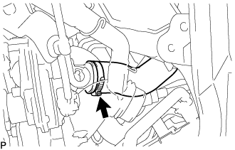
DISCONNECT NO. 1 RADIATOR HOSE
-
Slide the clip and disconnect the No. 1 radiator hose from the water inlet.
-
-
REMOVE FAN AND GENERATOR V BELT
-
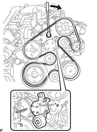
Обозначения на рисунке *a Технологическое отверстие *b Штырь Поворачивая натяжитель поликлинового ремня по часовой стрелке, совместите технологические отверстия натяжителя поликлинового ремня, а затем вставьте в технологические отверстия стержень диаметром 5,0 мм (0,197 дюйма), чтобы закрепить натяжитель поликлинового ремня на месте.
-
Снимите поликлиновой ремень вентилятора и генератора.
-
-
REMOVE V-RIBBED BELT TENSIONER ASSEMBLY
-
Remove the 3 bolts and V-ribbed belt tensioner assembly from the timing chain cover sub-assembly.
-
-
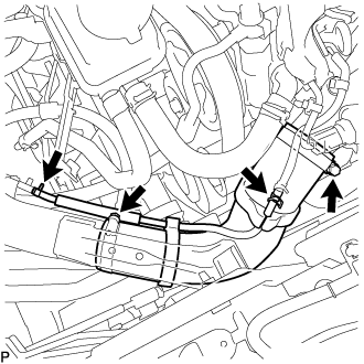
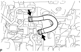
REMOVE NO. 2 FUEL HOSE
-
Slide the 2 clips and remove the No. 2 fuel hose from the supply pump assembly and No. 3 nozzle leakage pipe assembly.
-
-
REMOVE NO. 1 FUEL HOSE
-
Slide the 2 clips and remove the No. 1 fuel hose from the supply pump assembly and No. 2 fuel pipe.
-
-
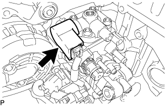
REMOVE FUEL INJECTION PUMP COVER SUB-ASSEMBLY
-
Remove the fuel injection pump cover sub-assembly from the supply pump assembly.
-
-
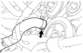
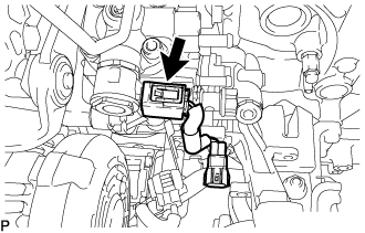
REMOVE FUEL PUMP MOTOR WIRE
-
Disconnect the fuel pump motor wire connector and remove the fuel pump motor wire.
-
-
REMOVE TIMING CHAIN COVER PLATE
-
Remove the 3 bolts and timing chain cover plate.
-
Remove the gasket.
-
-
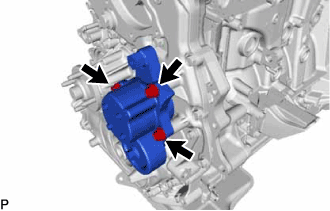
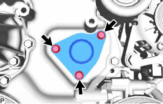
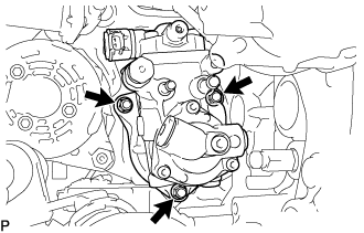
REMOVE SUPPLY PUMP ASSEMBLY
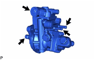
Note
-
Do not hold the supply pump assembly by the parts indicated by the arrows in the illustration.
-
With SST set, do not turn the crankshaft more than a half rotation.
-
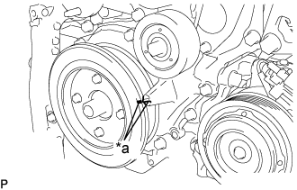
Text in Illustration *a Timing Mark Align the timing mark of the crankshaft pulley sub-assembly and timing chain cover by rotating the crankshaft clockwise.
-
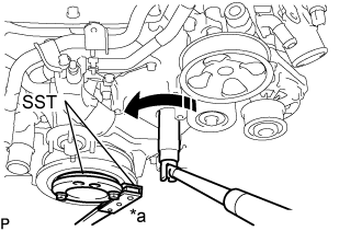
Text in Illustration *a Hold 
Turn Using SST, hold the crankshaft pulley assembly and loosen the fuel supply pump shaft nut.
- SST
- 09213-58014 ( 91551-80840 )
- 09330-00021
Note
Do not excessively loosen the supply pump shaft nut, otherwise SST cannot be installed.
Tech Tips
Rotate the supply pump shaft nut once to loosen it.
-
Loosen the 3 nuts from the supply pump assembly.
Note
Do not completely remove the nuts. Otherwise, the supply pump assembly may fall off.
-
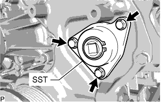
Install SST with the 3 bolts.
- SST
- 09241-11010
- Torque:
- 10 N*m { 102 kgf*cm, 7 ft.*lbf }
Note
Install SST with the bolts included with SST.
Tech Tips
-
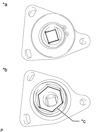
-
Make sure that the installation direction of SST is as shown in the illustration.
-
Align the hexagonal portion of SST with the supply pump shaft nut to install SST.
Text in Illustration *a Engine Front Side *b Engine Rear Side *c SST Hexagonal Portion
-
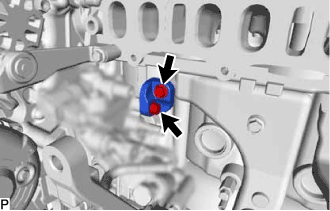
Remove the 2 bolts and No. 1 fuel pump bracket from the supply pump assembly and cylinder block sub-assembly.
-
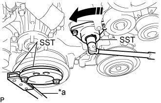
Text in Illustration *a Hold Turn Install the handle to SST. While holding the crankshaft pulley assembly in place with the crankshaft holding tool, turn the handle in the counterclockwise direction to disconnect the supply pump assembly.
- SST
- 09213-58014 ( 91551-80840 )
- 09241-11010
- 09330-00021
-
Remove the 3 nuts and supply pump assembly from the timing chain case assembly.
-
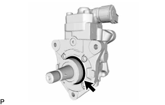
Remove the O-ring from the supply pump assembly.
-