OCCUPANT CLASSIFICATION SYSTEM, Diagnostic DTC:B1790
| DTC Code | DTC Name |
|---|---|
| B1790 | Center Airbag Sensor Assembly Communication Circuit Malfunction |
DESCRIPTION
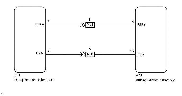
The airbag sensor assembly communication circuit consists of the occupant detection ECU and airbag sensor assembly.
DTC B1790 is stored when a malfunction is detected in the airbag sensor assembly communication circuit.
DTC No. |
Detection Item |
DTC Detection Condition |
Trouble Area |
|---|---|---|---|
B1790 |
Center Airbag Sensor Assembly Communication Circuit Malfunction |
|
|
When DTC B1650/32 is stored as a result of troubleshooting the airbag system, perform troubleshooting for DTC B1790 of the occupant classification system.
Use the GTS to check for DTCs of the occupant detection ECU, otherwise the DTCs cannot be read.
WIRING DIAGRAM
CAUTION / NOTICE / HINT
When disconnecting the cable, some systems need to be initialized after the cable is reconnected.
If troubleshooting (wire harness inspection) is difficult to perform, remove the front RH seat installation bolts to see the undersurface of the seat cushion.
In the above case, hold the seat so that it does not fall down. Holding the seat for a long period of time may cause problems, such as seat rail deformation. Hold the seat up only for as long as necessary.
PROCEDURE
CHECK DTC
Turn the power switch to on (IG), and wait for at least 60 seconds.
Clear the DTCs.
Body Electrical > Occupant Detection > Clear DTCs
Tip:First clear the DTCs stored in the occupant detection ECU, and then clear the DTCs stored in the airbag sensor assembly.
Use the GTS to clear the DTCs of the occupant detection ECU, otherwise the DTCs cannot be cleared.
Turn the power switch off.
Turn the power switch to on (IG), and wait for at least 60 seconds.
Check for DTCs.
Body Electrical > Occupant Detection > Trouble Codes
Result
Proceed to
DTC B1790 is not output
DTC B1790 is output
Tip:DTCs other than DTC B1790 may be output at this time, but they are not related to this check.
CHECK CONNECTION OF CONNECTOR
Turn the power switch off.
Disconnect the cable from the negative (-) auxiliary battery terminal, and wait for at least 90 seconds.
Check that the connectors are properly connected to the occupant detection ECU and airbag sensor assembly.
Result
Proceed to
Connectors are properly connected
Connectors are not properly connected
Connectors are not properly connected CONNECT CONNECTOR
CHECK CONNECTORS
-
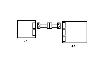
*1
Occupant Detection ECU
*2
Airbag Sensor Assembly
Disconnect the connectors from the airbag sensor assembly and occupant detection ECU.
Check that the connectors (on the airbag sensor assembly side and occupant detection ECU side) are not damaged.
Result
Proceed to
Connectors are not deformed or damaged
Connectors are deformed or damaged
Connectors are deformed or damaged REPLACE HARNESS AND CONNECTOR
-
CHECK AIRBAG SENSOR ASSEMBLY CIRCUIT
-
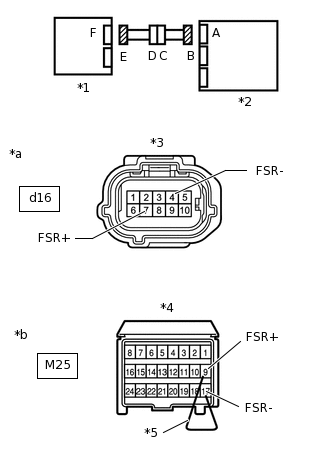
*1
Occupant Detection ECU
*2
Airbag Sensor Assembly
*3
Connector E
*4
Connector B
*5
Service Wire
*a
Front view of wire harness connector
(to Occupant Detection ECU)
*b
Rear view of wire harness connector
(to Airbag Sensor Assembly)
Connect the cable to the negative (-) auxiliary battery terminal, and wait for at least 2 seconds.
Turn the power switch to on (IG).
Measure the voltage according to the value(s) in the table below.
Standard Voltage
Tester Connection
Switch Condition
Specified Condition
d16-7 (FSR+) - Body ground
Power switch on (IG)
Below 1 V
d16-4 (FSR-) - Body ground
Turn the power switch off.
Disconnect the cable from the negative (-) auxiliary battery terminal, and wait for at least 90 seconds.
Using a service wire, connect terminals 9 (FSR+) and 17 (FSR-) of connector B.
Note:Do not forcibly insert the service wire into the terminals of the connector.
Measure the resistance according to the value(s) in the table below.
Standard Resistance
Tester Connection
Condition
Specified Condition
d16-7 (FSR+) - d16-4 (FSR-)
Always
Below 1 Ω
Disconnect the service wire from connector B.
Measure the resistance according to the value(s) in the table below.
Standard Resistance
Tester Connection
Condition
Specified Condition
d16-7 (FSR+) - d16-4 (FSR-)
Always
1 MΩ or higher
d16-7 (FSR+) - Body ground
d16-4 (FSR-) - Body ground
Result
Proceed to
OK
NG
NG CHECK FRONT SEAT WIRE RHClick here
-
CHECK DTC
Connect the connectors to the occupant detection ECU and airbag sensor assembly.
Connect the cable to the negative (-) auxiliary battery terminal, and wait for at least 2 seconds.
Turn the power switch to on (IG), and wait for at least 60 seconds.
Clear the DTCs.
Body Electrical > Occupant Detection > Clear DTCs
Tip:First clear the DTCs stored in the occupant detection ECU, and then clear the DTCs stored in the airbag sensor assembly.
Use the GTS to clear the DTCs of the occupant detection ECU, otherwise the DTCs cannot be cleared.
Turn the power switch off.
Turn the power switch to on (IG), and wait for at least 60 seconds.
Check for DTCs.
Body Electrical > Occupant Detection > Trouble Codes
Result
Proceed to
DTC B1790 is not output
DTC B1790 is output
Tip:DTCs other than DTC B1790 may be output at this time, but they are not related to this check.
REPLACE OCCUPANT DETECTION ECU
Turn the power switch off.
Disconnect the cable from the negative (-) auxiliary battery terminal, and wait for at least 90 seconds.
Replace the occupant detection ECU.
Tip:Perform the inspection using parts from a normal vehicle when possible.
Result
Proceed to
NEXT
PERFORM ZERO POINT CALIBRATION
Connect the cable to the negative (-) auxiliary battery terminal, and wait for at least 2 seconds.
Turn the power switch to on (IG).
Perform the zero point calibration.
Result
Proceed to
"Zero Point Calibration is complete." is displayed
PERFORM SENSITIVITY CHECK
Perform the sensitivity check.
Standard
27 to 33 kg (59.5 to 72.8 lb)
Result
Proceed to
NEXT
CHECK DTC
Clear the DTCs.
Body Electrical > Occupant Detection > Clear DTCs
Tip:First clear the DTCs stored in the occupant detection ECU, and then clear the DTCs stored in the airbag sensor assembly.
Use the GTS to clear the DTCs of the occupant detection ECU, otherwise the DTCs cannot be cleared.
Turn the power switch off.
Turn the power switch to on (IG), and wait for at least 60 seconds.
Check for DTCs.
Body Electrical > Occupant Detection > Trouble Codes
Result
Proceed to
DTC B1790 is not output
DTC B1790 is output
Tip:DTCs other than DTC B1790 may be output at this time, but they are not related to this check.
DTC B1790 is not output END (OCCUPANT DETECTION ECU WAS DEFECTIVE)
CHECK FRONT SEAT WIRE RH
-
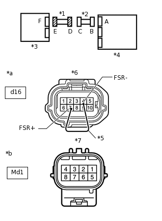
*1
Front Seat Wire RH
*2
Floor Wire
*3
Occupant Detection ECU
*4
Airbag Sensor Assembly
*5
Service Wire
*6
Connector E
*7
Connector D
*a
Front view of wire harness connector
(to Occupant Detection ECU)
*b
Front view of wire harness connector
(to Floor Wire)
Disconnect the front seat wire RH connector from the floor wire.
Connect the cable to the negative (-) auxiliary battery terminal, and wait for at least 2 seconds.
Turn the power switch to on (IG).
Measure the voltage according to the value(s) in the table below.
Standard Voltage
Tester Connection
Switch Condition
Specified Condition
Md1-1 - Body ground
Power switch on (IG)
Below 1 V
Md1-5 - Body ground
Turn the power switch off.
Disconnect the connector from the occupant detection ECU.
Using a service wire, connect terminals 7 (FSR+) and 4 (FSR-) of connector E.
Note:Do not forcibly insert the service wire into the terminals of the connector.
Measure the resistance according to the value(s) in the table below.
Standard Resistance
Tester Connection
Condition
Specified Condition
Md1-1 - Md1-5
Always
Below 1 Ω
Disconnect the service wire from connector E.
Measure the resistance according to the value(s) in the table below.
Standard Resistance
Tester Connection
Condition
Specified Condition
Md1-1 - Md1-5
Always
1 MΩ or higher
Md1-1 - Body ground
Md1-5 - Body ground
Result
Proceed to
OK
NG
OK REPLACE FLOOR WIRE
NG REPLACE FRONT SEAT WIRE RH
-