POWER WINDOW CONTROL SYSTEM Power Windows do not Operate at All
DESCRIPTION
If all of the power windows do not operate, the power window regulator master switch assembly may have no power or may be malfunctioning.
WIRING DIAGRAM
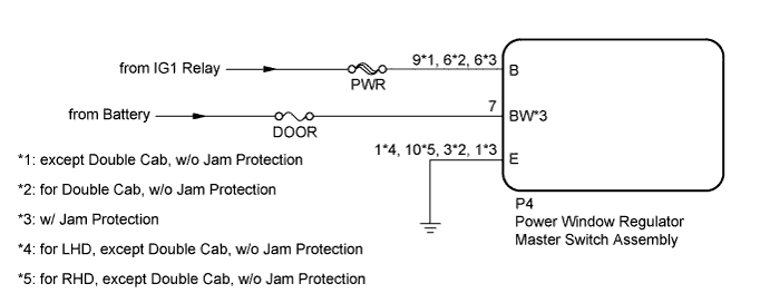
INSPECTION PROCEDURE
Note
Inspect the fuses for circuits related to this system before performing the following inspection procedure.
PROCEDURE
-
CHECK HARNESS AND CONNECTOR (POWER WINDOW REGULATOR MASTER SWITCH ASSEMBLY - BATTERY AND BODY GROUND)
-
except Double Cab, w/o Jam Protection:
-
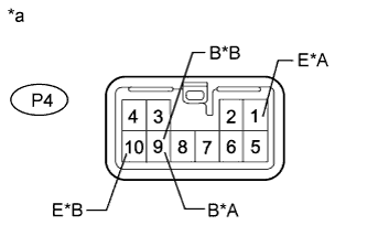
Text in Illustration *A for LHD *B for RHD *a Front view of wire harness connector
(to Power Window Regulator Master Switch Assembly)
Disconnect the P4 power window regulator master switch assembly connector.
-
Measure the voltage according to the value(s) in the table below.
Standard Voltage for LHD Tester Connection Switch Condition Specified Condition P4-9 (B) - Body ground Ignition switch ON 11 to 14 V P4-9 (B) - Body ground Ignition switch off Below 1 V for RHD Tester Connection Switch Condition Specified Condition P4-9 (B) - Body ground Ignition switch ON 11 to 14 V P4-9 (B) - Body ground Ignition switch off Below 1 V -
Measure the resistance according to the value(s) in the table below.
Standard Resistance for LHD Tester Connection Condition Specified Condition P4-1 (E) - Body ground Always Below 1 Ω for RHD Tester Connection Condition Specified Condition P4-10 (E) - Body ground Always Below 1 Ω
-
-
for Double Cab, w/o Jam Protection:
-
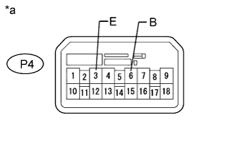
Text in Illustration *a Front view of wire harness connector
(to Power Window Regulator Master Switch Assembly)
Disconnect the P4 power window regulator master switch assembly connector.
-
Measure the voltage according to the value(s) in the table below.
Standard Voltage Tester Connection Switch Condition Specified Condition P4-6 (B) - Body ground Ignition switch ON 11 to 14 V P4-6 (B) - Body ground Ignition switch off Below 1 V -
Measure the resistance according to the value(s) in the table below.
Standard Resistance Tester Connection Condition Specified Condition P4-3 (E) - Body ground Always Below 1 Ω
-
-
w/ Jam Protection:
-
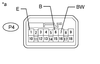
Text in Illustration *a Front view of wire harness connector
(to Power Window Regulator Master Switch Assembly)
Disconnect the P4 power window regulator master switch assembly connector.
-
Measure the voltage according to the value(s) in the table below.
Standard Voltage Tester Connection Condition Specified Condition P4-7 (BW) - Body ground Always 11 to 14 V P4-6 (B) - Body ground Ignition switch ON 11 to 14 V P4-6 (B) - Body ground Ignition switch off Below 1 V -
Measure the resistance according to the value(s) in the table below.
Standard Resistance Tester Connection Condition Specified Condition P4-1 (E) - Body ground Always Below 1 Ω
-
NG 
REPAIR OR REPLACE HARNESS OR CONNECTOR
OK 
REPLACE POWER WINDOW REGULATOR MASTER SWITCH ASSEMBLY
-