BRAKE BOOSTER(for LHD) INSTALLATION
PROCEDURE
INSTALL BRAKE BOOSTER GASKET
Install a new brake booster gasket to the brake booster assembly.
INSTALL BRAKE BOOSTER ASSEMBLY
Temporarily install the brake booster assembly to the vehicle body.
Note:Do not apply excessive force to the brake lines or refrigerant lines.
Temporarily install the lock nut and brake master cylinder push rod clevis to the brake booster assembly.
Note:Fully tighten the lock nut when adjusting the brake pedal height.
-
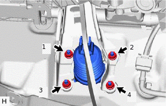
Install the 4 nuts to secure the brake booster assembly.
12.7 N*m
130 kgf*cm
9 ft.*lbf
Note:Tighten the 4 nuts in the order shown in the illustration.
w/ Stop and Start System:
Connect the connector to the vacuum sensor assembly.
INSTALL FRONT NO. 1 BRAKE TUBE WAY
Install the front No. 1 brake tube way to the vehicle body with the bolt.
7.0 N*m
71 kgf*cm
62 in.*lbf
INSTALL NO. 3 BRAKE TUBE CLAMP
for 1ND-TV, 8NR-FTS:
Engage the clamp to install a new No. 3 brake tube clamp.
Engage the clamp to install a new No. 3 brake tube clamp.
for 1ND-TV, 8NR-FTS:
Engage the 2 claws to install the brake tube heat insulator to the No. 3 brake tube clamp.
CONNECT CHECK VALVE TO CONNECTOR TUBE HOSE
Connect the check valve to connector tube hose to the brake booster assembly and slide the clip to secure it.
INSTALL NO. 3 HEATER BRACKET SUB-ASSEMBLY (w/ Combustion Type Power Heater)
Install the No. 3 heater bracket sub-assembly with the nut.
9.8 N*m
100 kgf*cm
87 in.*lbf
INSTALL HEATER PUMP ASSEMBLY (w/ Combustion Type Power Heater)
for 1ND-TV:Click here
for 1WW:Click here
INSTALL PUSH ROD PIN
INSTALL BRAKE PEDAL RETURN SPRING
INSTALL NO. 1 INSTRUMENT PANEL UNDER COVER SUB-ASSEMBLY (w/ Instrument Panel Under Cover)
for Sedan:Click hereClick here
for Hatchback, Wagon:Click here
INSTALL BRAKE ACTUATOR ASSEMBLY
INSTALL BRAKE MASTER CYLINDER SUB-ASSEMBLY
INSPECT AND ADJUST BRAKE PEDAL