VEHICLE STABILITY CONTROL SYSTEM Skid Control Buzzer Circuit
| DTC Code | DTC Name |
|---|---|
| Skid Control Buzzer Circuit |
DESCRIPTION
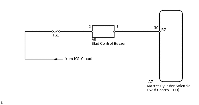
The skid control buzzer sounds upon receiving a signal from the skid control ECU.
WIRING DIAGRAM
CAUTION / NOTICE / HINT
When replacing the master cylinder solenoid, perform calibration (Click here).
PROCEDURE
PERFORM ACTIVE TEST USING INTELLIGENT TESTER (DSS SIGNAL BUZZER)
Turn the engine switch off.
Connect the intelligent tester to the DLC3.
Turn the engine switch on (IG).
Turn the intelligent tester on.
Enter the following menus: Chassis / ABS/VSC/TRC / Active Test.
Chassis > ABS/VSC/TRC > Active Test
Tester Display
Measurement Item
Control Range
Diagnostic Note
DSS Signal Buzzer
Skid control buzzer
Buzzer ON/OFF
The buzzer can be heard.
Check that the skid control buzzer sounds/stops when turning the skid control buzzer on/off by using the intelligent tester.
Result
Result
Proceed to
Buzzer does not sound or sounds constantly
A
Buzzer sounds/stops
B
CHECK TERMINAL VOLTAGE (IG1)
Disconnect the A9 skid control buzzer connector.
-
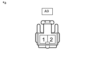
*a
Front view of wire harness connector
(to Skid Control Buzzer)
Measure the voltage according to the value(s) in the table below.
Standard Voltage
Tester Connection
Switch Condition
Specified Condition
A9-2 - Body ground
Engine switch on (IG)
11 to 14 V
Result
Result
OK
NG
NG REPAIR OR REPLACE HARNESS OR CONNECTOR
INSPECT SKID CONTROL BUZZER
Remove the skid control buzzer.
-
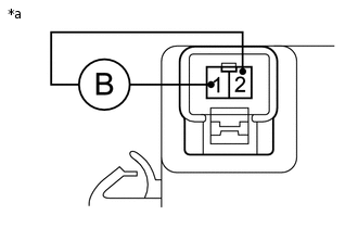
*a
Component without harness connected
(Skid Control Buzzer)
Apply battery voltage to the skid control buzzer, and check that the buzzer sounds.
Standard Resistance
Measurement Condition
Specified Condition
Battery positive (+) voltage - Terminal 2
Skid control buzzer sounds
Battery negative (-) voltage - Terminal 1
Result
Result
OK
NG
CHECK HARNESS AND CONNECTOR (SKID CONTROL BUZZER - SKID CONTROL ECU)
Disconnect the A7 skid control ECU connector.
Disconnect the A9 skid control buzzer connector.
Measure the resistance according to the value(s) in the table below.
Standard Resistance
Tester Connection
Condition
Specified Condition
A7-30 (BZ) - A9-1
Always
Below 1 Ω
A7-30 (BZ) - Body ground
Always
10 kΩ or higher
Result
Result
OK
NG
NG REPAIR OR REPLACE HARNESS OR CONNECTOR