ENGINE OIL COOLER (w/ EGR Cooler) REMOVAL
Note
-
When replacing the injectors (including shuffling the injectors between the cylinders), common rail or cylinder head, it is necessary to replace the injection pipes with new ones.
-
When replacing the fuel supply pump, common rail, cylinder block, cylinder head, cylinder head gasket or timing gear case, it is necessary to replace the fuel inlet pipe with a new one.
-
DISCONNECT CABLE FROM NEGATIVE BATTERY TERMINAL
CAUTION:
Wait at least 90 seconds after disconnecting the cable from the negative (-) battery terminal to prevent airbag activation.
Note
When disconnecting the cable, some systems need to be initialized after the cable is reconnected Click here.
-
REMOVE NO. 1 ENGINE UNDER COVER (for 4WD)
-
Remove the 4 bolts and No. 1 engine under cover.
-
-
REMOVE NO. 2 ENGINE UNDER COVER (for 4WD)
-
Remove the 2 bolts and No. 2 engine under cover.
-
-
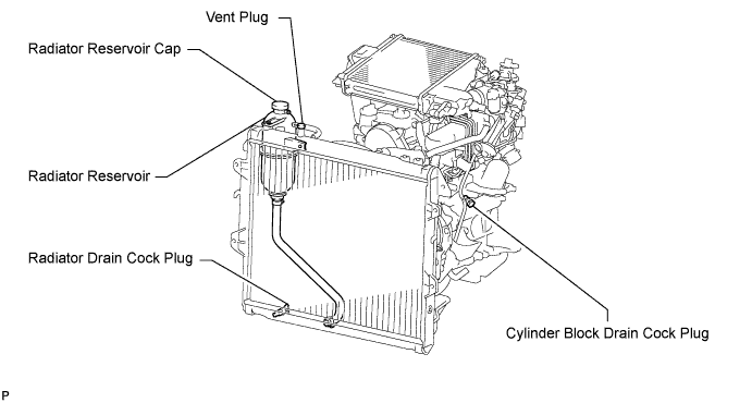
DRAIN ENGINE COOLANT
CAUTION:
Do not remove the radiator reservoir cap while the engine and radiator are still hot. Pressurized, hot engine coolant and steam may be released and cause serious burns.
-
Loosen the radiator drain cock plug.
Tech Tips
Collect the coolant in a container and dispose of it according to the regulations in your area.
-

Drain the coolant by removing the reservoir cap and, using a wrench, remove the vent plug.
-
Loosen the cylinder block drain cock plug.
-
-
DRAIN ENGINE OIL
-
Remove the oil filler cap.
-
Remove the oil drain plug, and drain the engine oil from the oil pan.
Note
Collect the oil in an oil disposal container.
-
-
LOOSEN FUEL TANK CAP ASSEMBLY
-
DRAIN FUEL
-
REMOVE EGR COOLER WITH ELECTRIC EGR CONTROL VALVE AND NO. 2 EGR VALVE
-
Remove the EGR cooler with electric EGR control valve and No. 2 EGR valve Click here.
-
-
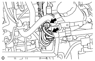
REMOVE NO. 4 INJECTION PIPE
-
Remove the bolt and disconnect the injection pipe clamp.
-
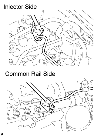
Using a 17 mm union nut wrench, loosen the union nuts and remove the No. 4 injection pipe.
-
-
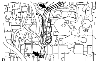
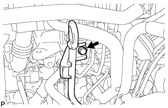
REMOVE OIL DIPSTICK GUIDE
-
Remove the bolt and injection pipe clamp.
-
Remove the bolt and guide.
-
Remove the O-ring from the guide.
-
-
REMOVE MANIFOLD STAY
-
Disconnect the 2 connectors.
-
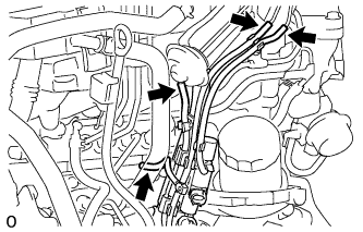
Disconnect the 4 vacuum hoses.
-
Remove the 2 bolts and manifold stay with VSV.
-
-
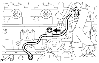
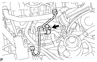
REMOVE NO. 2 NOZZLE LEAKAGE PIPE ASSEMBLY
-
Disconnect the 3 fuel hoses.
-
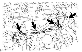
Remove the check valve, 3 bolts, leakage pipe and gasket.
-
-
REMOVE FUEL INLET PIPE SUB-ASSEMBLY
-
Remove the bolt and clamp.
-
Remove the bolt and oil level gauge guide.
-
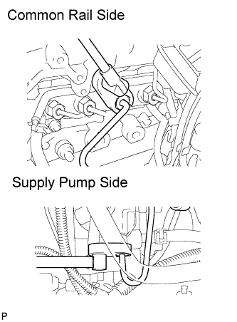
Using a 17 mm union nut wrench, loosen the union nuts and remove the fuel inlet pipe.
-
-
REMOVE NO. 2 INTAKE MANIFOLD INSULATOR
-
REMOVE COMMON RAIL ASSEMBLY
-
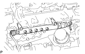
Disconnect the 2 connectors.
-
Remove the 2 bolts, common rail and insulator.
Note
Do not remove the pressure discharge valve and pressure sensor.
-
-
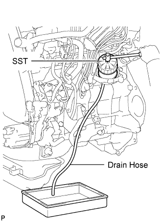
REMOVE OIL FILTER SUB-ASSEMBLY
-
Using SST, remove the oil filter.
- SST
- 09228-07501
Tech Tips
Insert the drain hose in the oil cooler cover. Put the disposal container beneath the drain hose to collect the oil from the oil filter cover.
-
-
REMOVE STARTER ASSEMBLY
-
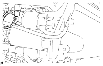
Disconnect the starter connector.
-
Remove the nut and disconnect the starter wire.
-
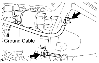
Remove the 2 bolts and disconnect the ground wire.
-
Remove the stater.
-
-
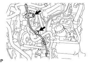
REMOVE FUEL SUPPLY PUMP ASSEMBLY
-
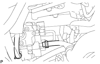
Disconnect the 2 fuel hoses.
-
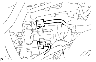
Disconnect the 2 connectors.
-
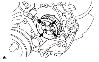
Remove the 4 bolts indicated by the arrows in the illustration.
-
Remove the No. 2 camshaft timing pulley flange and pump drive shaft pulley.
-
Remove the set nut and O-ring while holding the crankshaft pulley by using SST.
- SST
- 09213-58013
- 09330-00021
-
Loosen the 2 nuts.
-
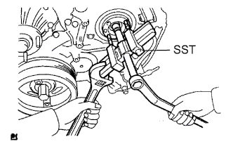
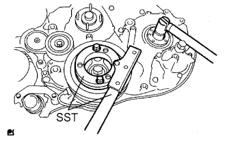
Using SST, disconnect the pump from the injection gear.
- SST
- 09950-50013 ( 09951-05010, 09952-05010, 09953-05020, 09954-05021 )
Note
Apply lubricant to the threads and tip of SST (center bolt) before using it.
-
Remove the 2 nuts and pump.
Note
-
Do not hold the pump or carry it holding the pipe.
-
The pump must be kept horizontal.
-
-
Remove the O-ring.
-
-
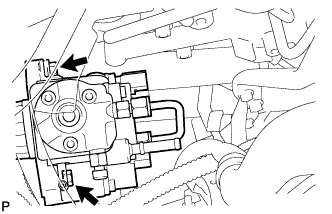
REMOVE OIL COOLER COVER SUB-ASSEMBLY
-
Disconnect the oil pressure switch connector and wire harness.
-
Remove the 2 nuts and No. 2 vacuum transmitting pipe.
-
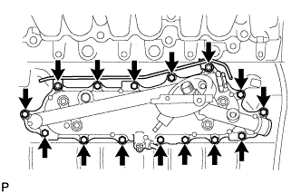
Remove the 13 bolts and oil cooler cover.
-
-
REMOVE OIL COOLER ASSEMBLY
-
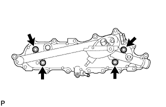
Loosen the 4 nuts first.
-
Partially tap out the oil cooler by tapping each nut head with a plastic-faced hammer.
-
Remove the 4 nuts, oil cooler and 2 gaskets.
-