REAR AIR CONDITIONING UNIT REASSEMBLY
PROCEDURE
-
INSTALL NO. 2 AIR CONDITIONING HARNESS ASSEMBLY
-
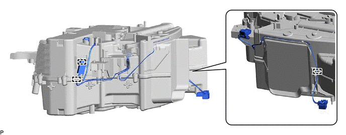
Engage the 2 claws to install the No. 2 air conditioning harness assembly.
-
-
INSTALL REAR EVAPORATOR SUB-ASSEMBLY
-
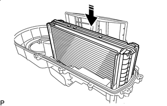

Install in this Direction Install the rear evaporator sub-assembly as shown in the illustration.
-
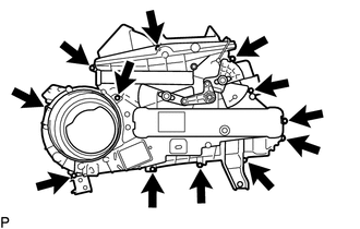
Install the rear cooling unit cover LH to the rear cooling unit cover RH with the 12 screws.
-
Engage each clamp.
-
-
INSTALL HEATER RADIATOR UNIT SUB-ASSEMBLY
-
Install in this Direction Install the heater radiator unit sub-assembly as shown in the illustration.
-
-
INSTALL COOLER UNIT CLAMP
-
Install the cooler unit clamp with the 2 screws.
-
-
INSTALL NO. 3 COOLING UNIT BRACKET
-
Install the No. 3 cooling unit bracket with the 2 screws.
-
-
INSTALL NO. 2 COOLING UNIT BRACKET
-
Install the No. 2 cooling unit bracket with the 2 screws.
-
-
INSTALL NO. 1 COOLING UNIT BRACKET
-
Install the No. 1 cooling unit bracket with the 3 screws.
-
-
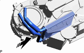
INSTALL REAR COOLING UNIT EXPANSION VALVE
-
Remove the vinyl tape from the rear cooling unit expansion valve and rear evaporator sub-assembly.
-
Sufficiently apply compressor oil to 2 new O-rings and the fitting surfaces of the rear cooling unit expansion valve.
Compressor Oil ND-OIL 8 or equivalent -
Install the 2 O-rings to the air conditioner tube and accessory assembly.
Note
Keep the O-rings and O-ring fitting surface free of foreign matter.
-
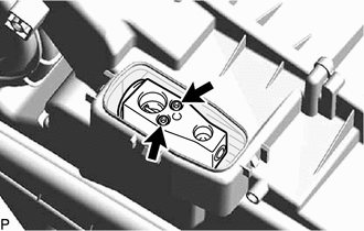
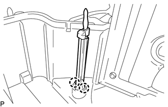
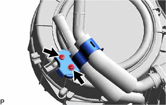
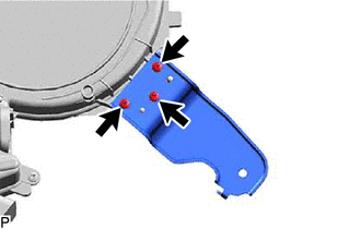
Using a 4 mm hexagon socket wrench, install the rear cooling unit expansion valve with the 2 hexagon bolts.
- Torque:
- 3.5 N*m { 36 kgf*cm, 31 in.*lbf }
-
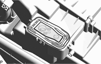
Install the grommet.
-
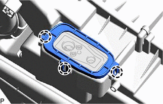
Engage the 3 claws to install the plate.
-
-
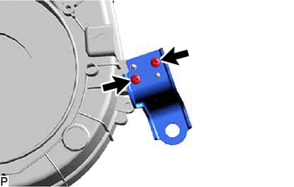
INSTALL REAR NO. 1 COOLING UNIT DAMPER SERVO SUB-ASSEMBLY
-
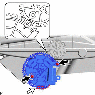
*a Reference Point Using the reference points, install the rear No. 1 cooling damper servo sub-assembly with the 2 screws.
-
Connect the connector.
-
-
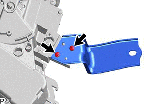
INSTALL REAR NO. 2 COOLING UNIT DAMPER SERVO SUB-ASSEMBLY
-
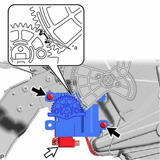
*a Reference Point Using the reference points, install the rear No. 2 cooling damper servo sub-assembly with the 2 screws.
-
Connect the connector.
-
-
INSTALL BLOWER MOTOR CONTROL
-
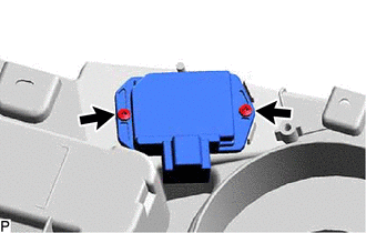
Install the blower motor control with the 2 screws.
-
-
INSTALL REAR BLOWER MOTOR WITH FAN SUB-ASSEMBLY
-
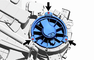
Install the rear blower motor with fan sub-assembly with the 3 screws.
Note
Replace the rear blower motor with fan sub-assembly if it has been dropped or subjected to a severe impact.
-