БЛОК МЕХАНИЧЕСКОЙ ТРАНСМИССИИ РАЗБОРКА

PROCEDURE
-
REMOVE MANUAL TRANSMISSION FILLER PLUG
-
Remove the manual transmission filler plug and gasket from the manual transmission case.
-
-
REMOVE DRAIN PLUG SUB-ASSEMBLY
-
Remove the drain plug sub-assembly and gasket from the manual transmission case.
-
-
REMOVE CLUTCH RELEASE FORK BOOT
-
REMOVE CLUTCH RELEASE BEARING ASSEMBLY
-
REMOVE RELEASE FORK SUPPORT
-
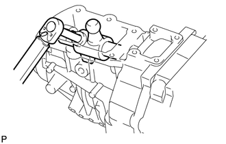
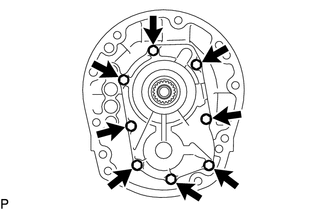
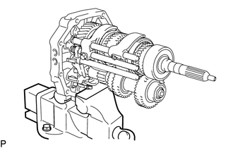
REMOVE CLUTCH HOUSING
-
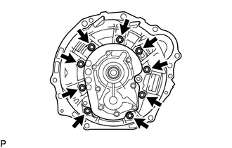
Remove the 9 bolts.
-
Using a plastic-faced hammer, tap off the clutch housing from the manual transmission case.
-
-
REMOVE BACK-UP LIGHT SWITCH ASSEMBLY
-
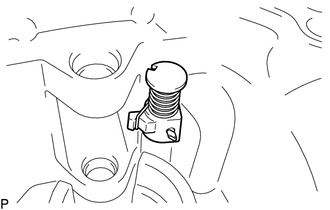
REMOVE REVERSE RESTRICT PIN ASSEMBLY
-
Remove the 2 reverse restrict pin assemblies from the extension housing sub-assembly.
-
-
REMOVE FLOOR SHIFT CONTROL SHIFT LEVER RETAINER SUB-ASSEMBLY
-
Remove the 6 bolts.
-
Remove the floor shift control shift lever retainer sub-assembly.
-
Remove the control shift lever retainer gasket.
-
-
REMOVE EXTENSION HOUSING SUB-ASSEMBLY
-
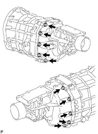
Remove the 10 bolts.
-
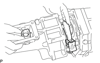
Using a plastic-faced hammer, tap the extension housing off of the intermediate plate. Make sure to remove the shift and select lever from the shift fork shafts before completely removing the extension housing sub-assembly.
-
-
REMOVE EXTENSION HOUSING DUST DEFLECTOR
-
Remove the bolt from the shift lever housing.
-
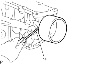
*a Protective Tape Using a screwdriver, pry out the extension housing dust deflector.
Note
Be careful not to damage the extension housing dust deflector.
Tech Tips
Put tape on the screwdriver tip before use.
-
-
REMOVE NO. 2 EXTENSION HOUSING OIL RECEIVER PIPE
-
Remove the No. 2 extension housing oil receiver pipe from the extension housing sub-assembly.
-
-
REMOVE NO. 1 EXTENSION HOUSING OIL RECEIVER PIPE
-
Remove the bolt and No. 1 extension housing oil receiver pipe.
-
-
REMOVE REVERSE RESTRICT PIN
-
Using a T40 ''TORX'' socket wrench, remove the plug.
-
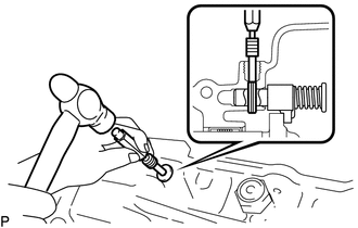
Using a 5 mm pin punch and hammer, tap out the reverse restrict slotted pin.
-
Remove the reverse restrict pin.
-
-
REMOVE MANUAL TRANSMISSION EXTENSION HOUSING OIL SEAL
-
REMOVE FRONT BEARING RETAINER
-
Remove the 8 bolts.
-
Using a brass bar and hammer, tap off the front bearing retainer from the manual transmission case.
-
-
REMOVE TRANSMISSION FRONT BEARING RETAINER OIL SEAL
-
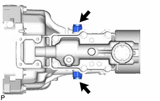
REMOVE FRONT BEARING SHAFT SNAP RING
-
Using a snap ring expander, remove the front bearing shaft snap ring from the manual transmission case.
-
-
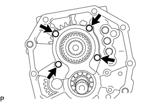
REMOVE COUNTER GEAR FRONT BEARING SNAP RING
-
Using a snap ring expander, remove the counter gear front bearing snap ring from the manual transmission case.
-
-
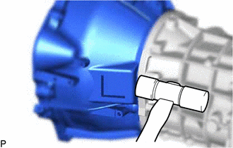
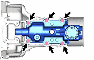
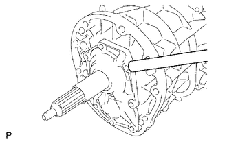
REMOVE MANUAL TRANSMISSION CASE
-
Using a brass bar and hammer, tap off the manual transmission case from the intermediate plate.
-
-
REMOVE TRANSMISSION MAGNET
-
Remove the transmission magnet from the intermediate plate.
-
-
SECURE INTERMEDIATE PLATE
-
Secure the intermediate plate in a vise between aluminum plates.
-
-
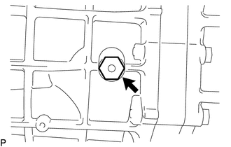
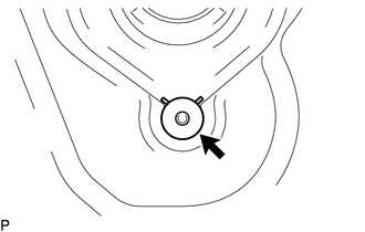
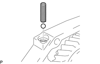
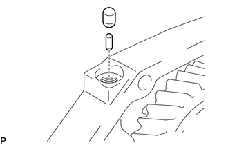
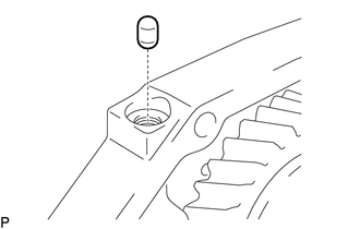
REMOVE SHIFT DETENT BALL PLUG
-
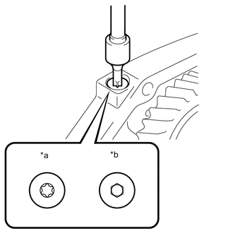
*a for Type A *b for Type B Remove the shift detent ball plug from the intermediate plate.
-
for Type A:
Using a T40 ''TORX'' socket wrench, remove the shift detent ball plug from the intermediate plate.
-
for Type B:
Using a 6 mm hexagon socket wrench, remove the shift detent ball plug from the intermediate plate.
-
-
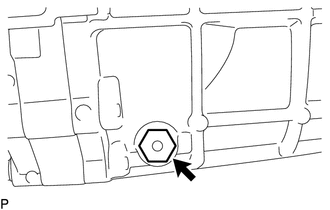
Using a magnet hand, remove the shift detent ball compression spring and shift detent ball from the intermediate plate.
-
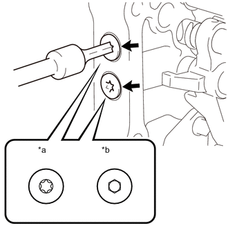
*a for Type A *b for Type B Remove the shift detent ball plug from the intermediate plate.
-
for Type A:
Using a T40 ''TORX'' socket wrench, remove the 2 shift detent ball plugs from the intermediate plate.
-
for Type B:
Using a 6 mm hexagon socket wrench, remove the 2 shift detent ball plugs from the intermediate plate.
-
-
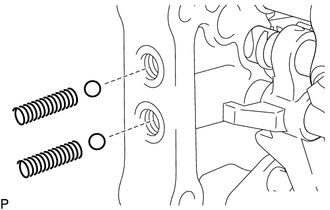
Using a magnet hand, remove the 2 shift detent ball compression springs and 2 shift detent balls from the intermediate plate.
-
-
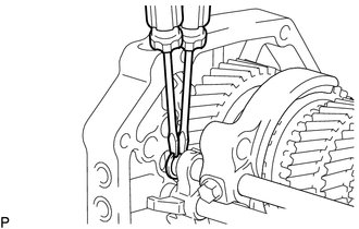
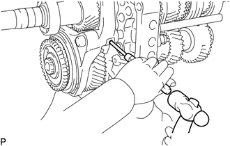
REMOVE NO. 2 GEAR SHIFT FORK SHAFT
-
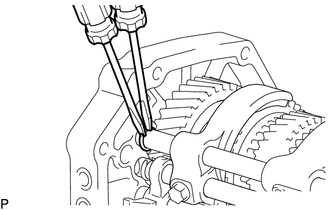
Using 2 screwdrivers and a hammer, tap off the shift fork shaft snap ring from the No. 2 gear shift fork shaft.
Note
Use a cloth to prevent the shift fork shaft snap ring from flying off.
-
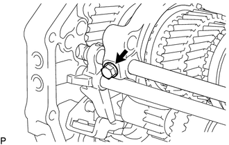
Remove the bolt from the No. 2 gear shift fork.
-
Remove the No. 2 gear shift fork shaft from the intermediate plate.
-
Remove the No. 2 gear shift fork from the No. 2 transmission hub sleeve.
-
Using a magnet hand, remove the No. 1 shift interlock roller and shift interlock pin from the intermediate plate.
-
-
REMOVE NO. 1 GEAR SHIFT FORK SHAFT
-
Using 2 screwdrivers and a hammer, tap off the shift fork shaft snap ring from the No. 1 gear shift fork shaft.
Note
Use a cloth to prevent the shift fork shaft snap ring from flying off.
-
Remove the bolt from the No. 1 gear shift fork.
-
Remove the No. 1 gear shift fork shaft from the intermediate plate.
-
Remove the No. 1 gear shift fork from the reverse gear.
-
Using a magnet hand, remove the No. 1 shift interlock roller from the intermediate plate.
-
-
REMOVE NO. 3 GEAR SHIFT FORK SHAFT
-
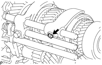
Using a 5 mm pin punch and hammer, tap out the shift fork set slotted spring pin from the No. 3 gear shift fork shaft.
-
Using 2 screwdrivers and a hammer, tap off the shift fork shaft snap ring from the No. 3 gear shift fork shaft.
Note
Use a cloth to prevent the shift fork shaft snap ring from flying off.
-
Using a magnet hand, remove the No. 1 shift interlock roller from the reverse shift fork.
-
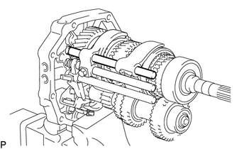
Remove the No. 3 gear shift fork and No. 3 gear shift fork shaft from the intermediate plate.
-
-
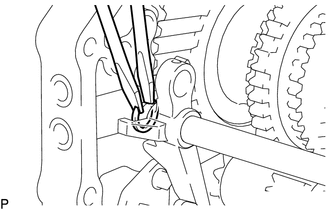
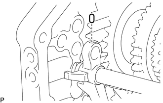
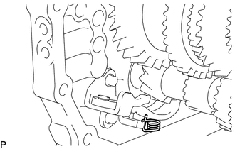
REMOVE REVERSE SHIFT FORK
-
Remove the reverse shift fork from the reverse shift arm.
-
-
REMOVE REVERSE SHIFT ARM BRACKET
-
Remove the torsion spring from the reverse shift arm bracket.
-
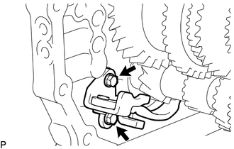
Remove the 2 bolts and reverse shift arm bracket from the intermediate plate.
-
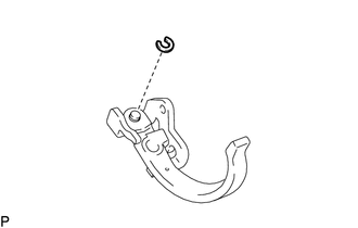
Using a screwdriver, remove the snap ring from the reverse shift arm bracket.
-
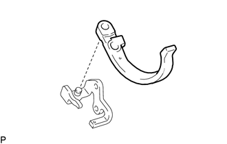
Remove the reverse shift arm from the reverse shift arm bracket.
-
-
REMOVE SPEEDOMETER DRIVE GEAR
-
Using snap ring pliers, remove the snap ring.
-
Remove the speedmeter drive gear.
-
Using a magnet hand, remove the steel ball.
-
Using snap ring pliers, remove the snap ring.
-
-
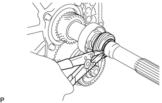
REMOVE OUTPUT SHAFT REAR BEARING
-
Using 2 screwdrivers and a hammer, tap off the shaft snap ring from the output shaft.
-
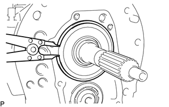
Using SST, remove the output shaft rear bearing and output shaft spacer from the output shaft.
- SST
- 09950-40011 ( 09951-04010, 09952-04010, 09953-04020, 09954-04010, 09955-04051, 09957-04010, 09958-04011 )
-
-
INSPECT COUNTERSHAFT 5TH GEAR THRUST CLEARANCE
-
INSPECT COUNTERSHAFT 5TH GEAR RADIAL CLEARANCE
-
REMOVE COUNTER SHAFT REAR SNAP RING
-
Using 2 screwdrivers and a hammer, tap off the counter shaft rear snap ring from the countershaft 5th gear.
-
-
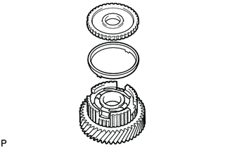
REMOVE NO. 3 TRANSMISSION HUB SLEEVE
-
Remove the No. 3 transmission hub sleeve from the countershaft 5th gear.
-
-
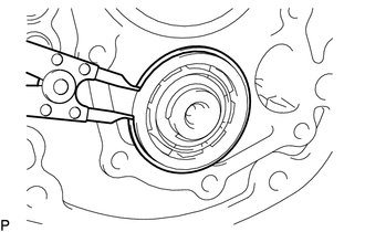
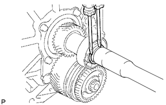
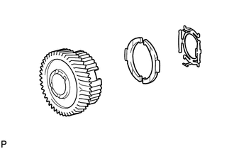
REMOVE COUNTERSHAFT 5TH GEAR
-
Using SST, remove the countershaft 5th gear together with the 2 No. 3 synchromesh shifting keys, No. 3 synchromesh shifting key spring, No. 3 synchronizer ring and No. 5 gear spline piece from the countergear.
- SST
- 09950-40011 ( 09951-04020, 09952-04010, 09953-04020, 09954-04010, 09955-04021, 09957-04010, 09958-04011 )
-
-
REMOVE NO. 5 GEAR SPLINE PIECE
-
Remove the No. 5 gear spline piece from the countershaft 5th gear.
-
-
REMOVE NO. 3 SYNCHRONIZER RING
-
Remove the No. 3 synchronizer ring from the countershaft 5th gear.
-
-
REMOVE COUNTER 5TH GEAR BEARING
-
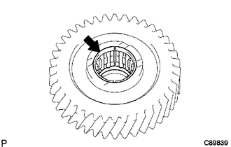
Remove the counter 5th gear bearing from the countershaft 5th gear.
-
-
REMOVE NO. 3 SYNCHROMESH SHIFTING KEY
-
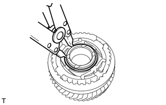
Using a snap ring expander, remove the shaft snap ring.
-
Remove the No. 3 synchromesh shifting key spring and 2 No. 3 synchromesh shifting keys from the countershaft 5th gear.
-
-
REMOVE 5TH GEAR THRUST WASHER
-
Remove the 5th gear thrust washer from the counter gear.
-
-
REMOVE 5TH GEAR THRUST WASHER PIN
-
Remove the 5th gear thrust washer pin from the counter gear.
-
-
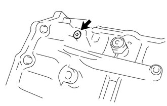
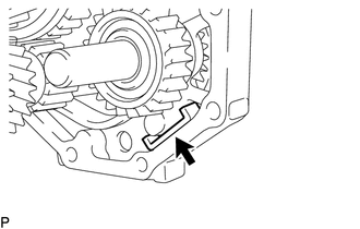
REMOVE OUTPUT SHAFT REAR BEARING RETAINER
-
Remove the 4 bolts and output shaft rear bearing retainer from the intermediate plate.
-
-
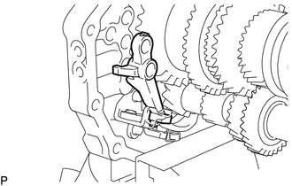
REMOVE REVERSE IDLER GEAR SUB-ASSEMBLY
-
Pull out the reverse idler gear shaft and reverse idler gear sub-assembly from the intermediate plate.
-
-
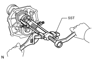
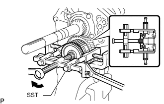
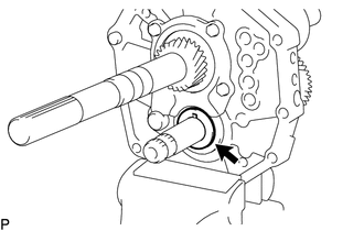
REMOVE COUNTER SHAFT REAR BEARING
-
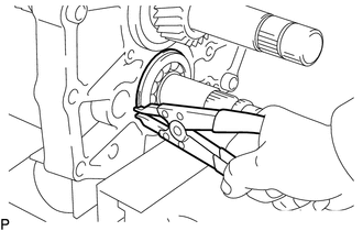
Using a snap ring expander, remove the snap ring.
-
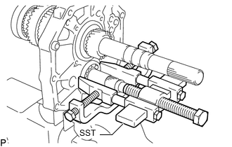
Using SST, remove the counter shaft rear bearing from the intermediate plate.
- SST
- 09950-40011 ( 09951-04010, 09952-04010, 09953-04020, 09954-04010, 09955-04011, 09957-04010, 09958-04011 )
Tech Tips
Remove the counter shaft rear bearing while tapping the tip of the counter gear so that the counter gear does not hit the side wall of the output shaft gear by being pushed forward.
-
-
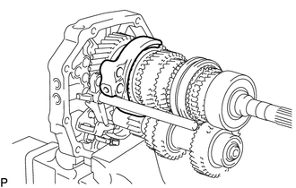
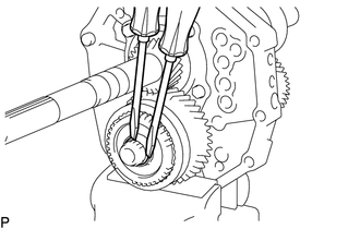
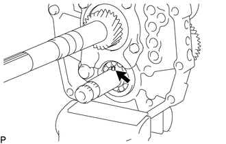
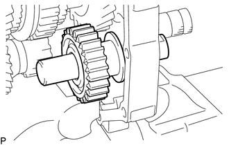
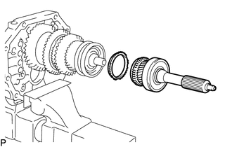
REMOVE COUNTER GEAR
-
Remove the counter gear from the intermediate plate.
-
-
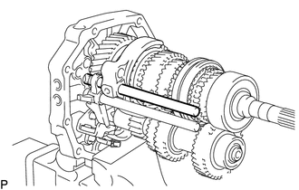
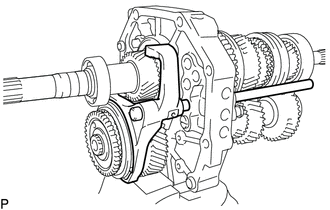
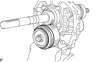
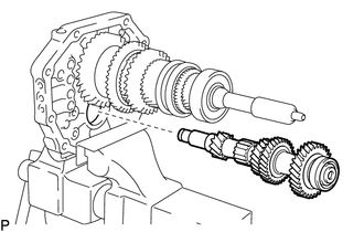
REMOVE INPUT SHAFT
-
Remove the input shaft and No. 2 synchronizer ring from the output shaft.
Note
Do not drop the input shaft bearing and No. 2 synchronizer ring.
-
-
INSPECT NO. 2 SYNCHRONIZER RING
-
REMOVE OUTPUT SHAFT BEARING SHAFT SNAP RING
-
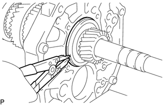
Using a snap ring expander, remove the output shaft bearing shaft snap ring from the output shaft.
-
-
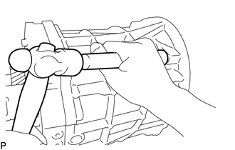
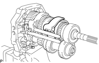
REMOVE OUTPUT SHAFT
-
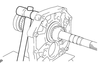
Using a plastic-faced hammer, remove the output shaft by tapping the intermediate plate.
-
-
REMOVE STRAIGHT PIN
Note
If a straight pin is deformed or its threads are damaged, replace it.
-
REMOVE RING PIN
Note
If a ring pin is deformed or its threads are damaged, replace it.
-
INSPECT NO. 3 SYNCHRONIZER RING
-
INSPECT NO. 3 TRANSMISSION HUB SLEEVE
-
INSPECT COUNTERSHAFT 5TH GEAR
-
INSPECT REVERSE IDLER GEAR SUB-ASSEMBLY