СИСТЕМА SFI, Diagnostic DTC:P0120/41, P0122/41, P0123/41, P0220/41, P0222/41, P0223/41, P2135/41
| DTC Code | DTC Name |
|---|---|
| P0120/41 | Throttle / Pedal Position Sensor / Switch "A" Circuit |
| P0122/41 | Throttle / Pedal Position Sensor / Switch "A" Circuit Low Input |
| P0123/41 | Throttle / Pedal Position Sensor / Switch "A" Circuit High Input |
| P0220/41 | Throttle / Pedal Position Sensor / Switch "B" Circuit |
| P0222/41 | Throttle / Pedal Position Sensor / Switch "B" Circuit Low Input |
| P0223/41 | Throttle / Pedal Position Sensor / Switch "B" Circuit High Input |
| P2135/41 | Throttle / Pedal Position Sensor / Switch "A" / "B" Voltage Correlation |
DESCRIPTION
Tech Tips
-
These DTCs are related to the throttle position sensor.
-
The Electronic Throttle Control System (ETCS) does not use a throttle cable.
-
This throttle position sensor is a non-contact type.
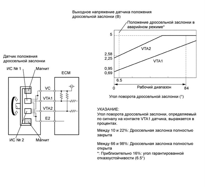
The throttle position sensor is mounted on the throttle body and it detects the opening angle of the throttle valve. This sensor is electronically controlled and uses Hall-effect elements so that accurate control and reliability can be obtained. The throttle position sensor has 2 sensor elements/signal outputs: VTA1 and VTA2. VTA1 is used to detect the throttle opening angle and VTA2 is used to detect a malfunction in VTA1. Voltage applied to VTA1 and VTA2 changes between 0 V and 5 V in proportion to the opening angle of the throttle valve. The ECM performs several checks to confirm proper operation of the throttle position sensor and VTA1.
The ECM judges the actual opening angle of the throttle valve from these signals input from terminals VTA1 and VTA2, and the ECM controls the throttle motor, which controls the throttle valve angle properly in response to driver input.
| DTC No. | DTC Detection Condition | Trouble Area |
|---|---|---|
| - | Conditions of DTC P0120/41, P0122/41, P0123/41, P0220/41, P0222/41 or P0223/41 continue for 2 seconds (open or short in throttle position sensor circuit) |
- |
| P0120/41 | Output voltage of VTA1 quickly fluctuates up and down beyond upper and lower malfunction thresholds (1 trip detection logic) |
|
| P0122/41 | VTA1 is 0.2 V or less (1 trip detection logic) |
|
| P0123/41 | VTA1 is 4.535 V or more (1 trip detection logic) |
|
| P0220/41 | Output voltages of VTA1 and VTA2 quickly fluctuate beyond their respective upper and lower malfunction thresholds (1 trip detection logic) |
|
| P0222/41 | VTA2 is 1.75 V or less (1 trip detection logic) |
|
| P0223/41 | VTA2 is 4.8 V or more, VTA1 is between 0.2 V and 2.02 V (1 trip detection logic) |
|
| P2135/41 | Condition (a) continues for 0.5 seconds or more, or condition (b) continues for 0.4 seconds or more: (1 trip detection logic)
|
|
Note
When a malfunction is detected, the throttle valve is locked at a certain opening angle. Also, all electronically controlled throttle operations are canceled until the system returns to normal and the ignition switch is turned OFF.
Tech Tips
-
When any of these DTCs is detected, check the throttle valve opening angle (Throttle Position and Throttle Position No. 2) using the intelligent tester.
-
The Throttle Position is the VTA1 signal (expressed as a percentage), and Throttle Position No. 2 is the VTA2 signal (expressed as a voltage).
| Reference (Normal condition) | |||||||||
|---|---|---|---|---|---|---|---|---|---|
|
MONITOR DESCRIPTION
The ECM uses the throttle position sensor to monitor the throttle valve opening angle.
-
There is a specific voltage difference expected between VTA1 and VTA2 for each throttle opening angle.
If the difference between VTA1 and VTA2 is incorrect, the ECM interprets this as a fault and will set a DTC.
-
VTA1 and VTA2 each have a specific voltage operating range.
If VTA1 or VTA2 is out of the normal operating range, the ECM interprets this as a fault and will set a DTC.
-
VTA1 and VTA2 should never have similar voltage levels.
If VTA1 is within 0.02 V of VTA2, the ECM interprets this as a short circuit in the throttle position sensor system and will set a DTC.
This monitor runs for 2 seconds (the first 2 seconds of engine idle) after the engine is started (1 trip detection logic).
FAIL-SAFE
If the ETCS is malfunctioning, the ECM cuts off the current to the throttle actuator. The throttle control valve returns to a predetermined throttle position (approximately 6.5°) by the force of the return spring.
Then, required engine power is calculated by using the ignition timing and accelerator pedal position. The engine is controlled by intermittent fuel-cut.
If the accelerator pedal is depressed firmly and slowly, the vehicle can be driven at minimum speed. If the accelerator pedal is depressed quickly, the vehicle may speed up and slow down erratically.
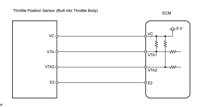
WIRING DIAGRAM
INSPECTION PROCEDURE
Tech Tips
-
If DTCs related to different systems that have terminal E2 as the ground terminal are output simultaneously, terminal E2 may have an open circuit.
-
Read freeze frame data using the intelligent tester. Freeze frame data records the engine conditions when malfunctions are detected. When troubleshooting, freeze frame data can help determine if the vehicle was moving or stationary, if the engine was warmed up or not, if the air-fuel ratio was lean or rich, and other data from the time the malfunction occurred.
When using intelligent tester:
PROCEDURE
-
READ DATA LIST (THROTTLE POSITION, THROTTLE POSITION NO. 2)
-
Connect the intelligent tester to the DLC3.
-
Turn the ignition switch ON and turn the intelligent tester ON.
-
Enter the following menus: Powertrain / Engine and ECT / Data List / Throttle Position and Throttle Position No. 2.
-
Read the values displayed on the intelligent tester.
Result TP (VTA1)
When AP Released
TP No. 2 (VTA2)
When AP Released
TP (VTA1)
When AP Depressed
TP No. 2 (VTA2)
When AP Depressed
Suspected Area Proceed to 0% 0 to 0.2 V 0% 0 to 0.2 V VC circuit open A 100% 4.5 to 4.98 V 100% 4.5 to 4.98 V E2 circuit open A 0 or 100% 2.1 to 3.1 V
(Fail-safe)
0% or 100% 2.1 to 3.1 V
(Fail-safe)
VTA1 circuit open or ground short A 10 to 22%
(Fail-safe)
0 to 0.2 V
or 4.5 to 4.98 V
10 to 22%
(Fail-safe)
0 to 0.2 V
or 4.5 to 4.98 V
VTA2 circuit open or ground short A 10 to 22% 2.1 to 3.1 V 66 to 98%
(Not fail-safe)
4.5 to 4.98 V
(Not fail-safe)
Throttle position sensor circuit is normal B Tech Tips
-
TP stands for Throttle Position, and AP stands for Accelerator Pedal.
-
VTA1 is expressed as a percentage, and VTA2 is expressed as a voltage.
-
B 
CHECK IF DTC OUTPUT RECURS (THROTTLE POSITION SENSOR DTCS) Click here
A 
-
-
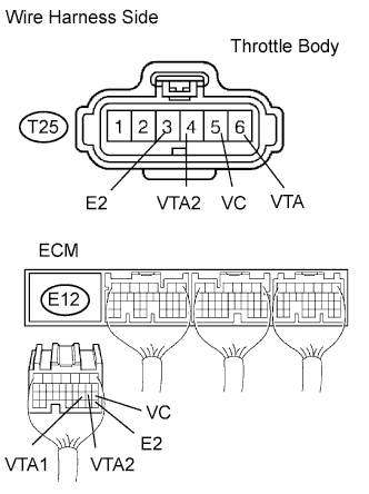
CHECK WIRE HARNESS (THROTTLE POSITION SENSOR - ECM)
-
Disconnect the T25 throttle body connector.
-
Disconnect the E12 ECM connector.
-
Measure the resistance of the wire harness side connectors.
Standard resistance Tester Connection Specified Condition T25-5 (VC) - E12-18 (VC) Below 1 Ω T25-6 (VTA) - E12-20 (VTA1) Below 1 Ω T25-4 (VTA2) - E12-19 (VTA2) Below 1 Ω T25-3 (E2) - E12-28 (E2) Below 1 Ω T25-5 (VC) or E12-18 (VC) - Body ground 10 kΩ or higher T25-6 (VTA) or E12-20 (VTA1) - Body ground 10 kΩ or higher T25-4 (VTA2) or E12-19 (VTA2) - Body ground 10 kΩ or higher
NG 
REPAIR OR REPLACE HARNESS AND CONNECTOR
OK
-
-
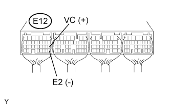
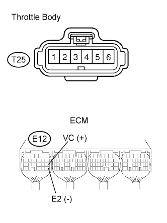
CHECK ECM (VC VOLTAGE)
-
Disconnect the T25 throttle body connector.
-
Turn the ignition switch ON and turn the intelligent tester ON.
-
Measure the voltage of the ECM connector.
Standard voltage Tester Connection Specified Condition E12-18 (VC) - E12-28 (E2) 4.5 to 5.0 V
NG
REPLACE ECM
OK
-
-
REPLACE THROTTLE BODY ASSEMBLY
NEXT
-
CHECK IF DTC OUTPUT RECURS (THROTTLE POSITION SENSOR DTCS)
-
Clear the DTCs Click here.
-
Start the engine.
-
Idle the engine for 15 seconds or more.
-
Connect the intelligent tester to the DLC3.
-
Turn the intelligent tester ON.
-
Enter the following menus: Powertrain / Engine and ECT / DTC.
-
Read DTCs.
Result Display (DTC Output) Proceed to One or more of P0120/41, P0122/41, P0123/41, P0220/41, P0222/41, P0223/41 and P2135/41 A No output B
B
SYSTEM OK
A 
REPLACE ECM
-
When not using intelligent tester:
PROCEDURE
-
CHECK WIRE HARNESS (THROTTLE POSITION SENSOR - ECM)
-
Disconnect the T25 throttle body connector.
-
Disconnect the E12 ECM connector.
-
Measure the resistance of the wire harness side connectors.
Standard resistance Tester Connection Specified Condition T25-5 (VC) - E12-18 (VC) Below 1 Ω T25-6 (VTA) - E12-20 (VTA1) Below 1 Ω T25-4 (VTA2) - E12-19 (VTA2) Below 1 Ω T25-3 (E2) - E12-28 (E2) Below 1 Ω T25-5 (VC) or E12-18 (VC) - Body ground 10 kΩ or higher T25-6 (VTA) or E12-20 (VTA1) - Body ground 10 kΩ or higher T25-4 (VTA2) or E12-19 (VTA2) - Body ground 10 kΩ or higher
NG
REPAIR OR REPLACE HARNESS AND CONNECTOR
OK
-
-
CHECK ECM (VC VOLTAGE)
-
Disconnect the T25 throttle body connector.
-
Turn the ignition switch ON.
-
Measure the voltage of the ECM connector.
Standard voltage Tester Connection Specified Condition E12-18 (VC) - E12-28 (E2) 4.5 to 5.5 V
NG
REPLACE ECM
OK
-
-
REPLACE THROTTLE BODY ASSEMBLY
NEXT
-
CHECK IF DTC OUTPUT RECURS (THROTTLE POSITION SENSOR DTCS)
-
Clear the DTCs Click here.
-
Start the engine.
-
Idle the engine for 15 seconds or more.
-
Read DTC Click here.
Result Display (DTC Output) Proceed to One or more of P0120/41, P0122/41, P0123/41, P0220/41, P0222/41, P0223/41 and P2135/41 A No output B
B
SYSTEM OK
A
REPLACE ECM
-