CYLINDER HEAD GASKET REMOVAL
PROCEDURE
REMOVE CHAIN SUB-ASSEMBLY
REMOVE CAMSHAFT BEARING CAP
REMOVE CAMSHAFT
-
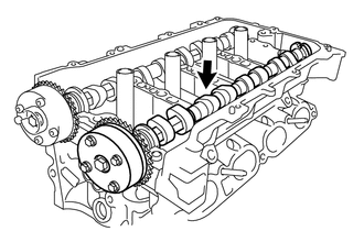
Remove the camshaft.
-
REMOVE NO. 2 CAMSHAFT
-
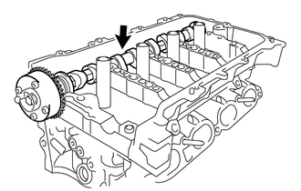
Remove the No. 2 camshaft.
-
REMOVE NO. 1 CAMSHAFT BEARING
REMOVE NO. 2 CAMSHAFT BEARING
REMOVE NO. 1 VALVE ROCKER ARM SUB-ASSEMBLY
REMOVE VALVE LASH ADJUSTER ASSEMBLY
REMOVE CAMSHAFT HOUSING SUB-ASSEMBLY
REMOVE CYLINDER HEAD SUB-ASSEMBLY
-
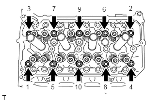
Using a 10 mm bi-hexagon wrench, uniformly loosen and remove the 10 cylinder head set bolts and 10 plate washers in several steps and in the order shown in the illustration.
Note:Removing the cylinder head set bolts in the wrong order may cause warpage or cracking of the cylinder head sub-assembly.
Do not drop the plate washers into the cylinder head sub-assembly.
Using a screwdriver with its tip wrapped with protective tape, pry between the cylinder head sub-assembly and cylinder block sub-assembly, and remove the cylinder head sub-assembly.
Note:Be careful not to damage the contact surfaces of the cylinder head sub-assembly and cylinder block sub-assembly.
-
REMOVE CYLINDER HEAD GASKET
-
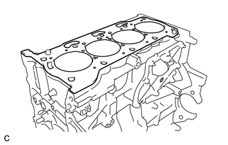
Remove the cylinder head gasket.
-
INSPECT NO. 1 VALVE ROCKER ARM SUB-ASSEMBLY
INSPECT VALVE LASH ADJUSTER ASSEMBLY
INSPECT CYLINDER HEAD SET BOLT