METER / GAUGE SYSTEM ON-VEHICLE INSPECTION
PROCEDURE
-
INSPECT COMBINATION METER SUB-ASSEMBLY
-
LED INITIAL CHECK
-
Check the illumination function of the warning or indicator lights listed below when turning the power switch on (IG).
OK Warning or Indicator Specified Condition
-
Water temperature
-
PCS*1
-
Headlight leveling*2
-
Hybrid system
-
Hybrid system overheat
-
Parking lock system
-
P position request
-
LED headlight*2
-
Hybrid battery
Warning or indicator light comes on for about 3 seconds after turning the power switch on (IG). SRS Warning light comes on for about 6 seconds after turning the power switch on (IG).
-
Oil pressure
-
Charge
-
EPS
-
MIL (Check engine warning light)
Indicator or warning light comes on when turning the power switch on (IG) before hybrid system starts.
-
Brake
-
Slip
-
ABS
-
Electronically controlled brake
Indicator or warning light comes on when turning the power switch on (IG) before hybrid system starts.*3 Indicator or warning light comes on when turning the power switch off to on (READY) for 3 seconds, then goes off.
-
*1: w/ Pre-crash Safety System
-
*2: w/ LED Headlight
-
*3: When turning the power switch on (IG), if it takes 3 seconds or more for the READY indicator light to illuminate, the warning or indicator light turns off right after the READY indicator light illuminates.
-
-
-
INSPECT SPEEDOMETER
Note
-
The combination meter sub-assembly receives the vehicle speed signal from the skid control ECU via CAN communication. Therefore, perform the following inspection referring to values on the Data List of the skid control ECU because it is the source of the vehicle speed signal.
-
The Data List values of the skid control ECU are used for this inspection. Therefore, make sure to perform the inspection after confirming that no DTCs are output from the brake control system.
-
If the tire size or tire inflation pressure is not within the specified range, or the tires are excessively worn, the speedometer indication error will increase. Therefore, make sure to perform the inspection after checking that the tire size, tire inflation pressure and tire wear are in the specified range.
-
Before starting the following inspection, check if the brake control system outputs the DTCs.
-
Check the values by referring to the table below.
ABS/VSC/TRAC Tester Display Measurement Item/Range Normal Condition Diagnostic Note Vehicle Speed Vehicle speed/Min.: 0 km/h (0 mph), Max.: 326 km/h (203 mph) Vehicle stopped: 0 km/h (0 mph) When driving at constant speed: No large fluctuations Reference: km/h (for Australia) GTS Indication (km/h) Acceptable Range (km/h) 20 20.7 to 24.7 40 41.4 to 45.9 60 62.1 to 66.6 80 82.8 to 87.3 100 103.4 to 106.4 120 124.1 to 128.1 140 144.8 to 149.8 160 165.5 to 170.5 180 186.2 to 191.2 Reference: km/h (except Australia) GTS Indication (km/h) Acceptable Range (km/h) 20 21.0 to 25.0 40 42.0 to 46.0 60 63.0 to 67.0 80 84.0 to 88.0 100 104.0 to 109.0 120 125.0 to 130.0 140 146.0 to 151.0 160 167.0 to 173.0 180 187.0 to 194.0 Reference: mph GTS Indication (mph) Acceptable Range (mph) 20 21.0 to 23.0 40 42.0 to 44.0 60 63.0 to 66.0 80 83.0 to 87.0 100 104.0 to 108.0 120 125.0 to 129.0 140 146.0 to 150.0
-
-
INSPECT HEADUP DISPLAY (COMBINATION METER MIRROR ECU)
Tech Tips
When the headup display position or illuminance has not adjusted properly, headup display may not be seen in the front glass. Before starting the following inspection, confirm the headup display position and illuminance.
-
Turn the power switch off.
-
Turn the power switch on (IG) while pressing and holding the headup display main switch.
-
Keep pressing the headup display main switch and turn the power switch off.
-
Keep pressing the headup display main switch and turn the power switch on (IG).
-
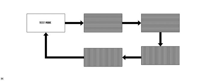
The headup display will show "TEST MODE".
-
Inspect the headup display as shown in the illustration.
-
Turn the power switch off to finish test mode.
Text in Illustration 
Headup display main switch pressed - -
-
-