REAR AXLE BEAM REMOVAL
PROCEDURE
REMOVE REAR WHEELS
REMOVE UPPER CONSOLE PANEL SUB-ASSEMBLY
for Hatchback, Wagon:Click here
for Sedan:Click here
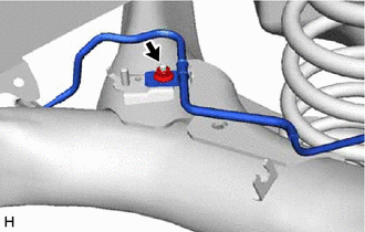
LOOSEN NO. 2 WIRE ADJUSTING NUT
DRAIN BRAKE FLUID
Note:If brake fluid leaks onto any painted surface, immediately wash it off.
REMOVE REAR FLOOR SIDE MEMBER COVER LH (w/ Cover)
-
Remove the 2 bolts, nut and rear floor side member cover LH.
-
REMOVE REAR FLOOR SIDE MEMBER COVER RH (w/ Cover)
-
Remove the 2 bolts, nut and rear floor side member cover RH.
-
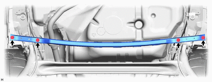
REMOVE REAR FLOOR SIDE MEMBER BRACE SUB-ASSEMBLY
Remove the 4 bolts and the rear floor side member brace sub-assembly.
SEPARATE SKID CONTROL SENSOR WIRE LH
SEPARATE SKID CONTROL SENSOR WIRE RH
Tip:Perform the same procedure as for the LH side.
SEPARATE NO. 3 PARKING BRAKE CABLE ASSEMBLY
Disconnect the No. 3 parking brake cable assembly.
-
Remove the bolt and separate the No. 3 parking brake cable assembly.
SEPARATE NO. 2 PARKING BRAKE CABLE ASSEMBLY
Tip:Perform the same procedure as for the No. 3 parking brake cable assembly.
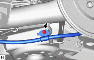
SEPARATE REAR BRAKE TUBE FLEXIBLE HOSE (for LH Side)
-
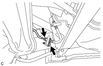
Using a union nut wrench, separate the rear brake tube flexible hose from the rear No. 4 brake tube.
Note:Do not kink or damage the brake tube.
Do not allow any foreign matter such as dirt or dust to enter the brake tube from the connecting parts.
Remove the bolt and separate the rear brake tube flexible hose from the rear axle beam assembly.
-
SEPARATE REAR BRAKE TUBE FLEXIBLE HOSE (for RH Side)
-
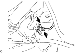
Using a union nut wrench, separate the rear brake tube flexible hose from the rear No. 3 brake tube.
Note:Do not kink or damage the brake tube.
Do not allow any foreign matter such as dirt or dust to enter the brake tube from the connecting parts.
Remove the clip and separate the rear brake tube flexible hose from the rear axle beam assembly.
-
REMOVE REAR DISC BRAKE CALIPER ASSEMBLY LH
-
Using a union nut wrench, separate the rear No. 4 brake tube while holding the rear flexible hose LH with a wrench.
Note:Do not kink or damage the brake tube.
Do not allow any foreign matter such as dirt or dust to enter the brake tube from the connecting parts.
-
Remove the clip and separate the rear flexible hose LH.
Remove the 2 bolts and rear disc brake caliper assembly LH with rear flexible hose LH.
-
REMOVE REAR DISC BRAKE CALIPER ASSEMBLY RH
Tip:Perform the same procedure as for the LH side.
REMOVE REAR DISC
Remove the 2 rear discs.
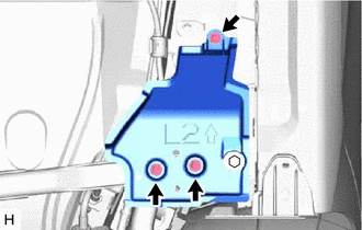
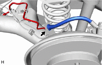
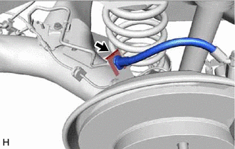
REMOVE REAR NO. 4 BRAKE TUBE
-
Remove the nut and rear No. 4 brake tube from the rear axle beam assembly.
-
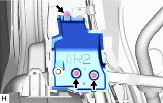
REMOVE REAR NO. 3 BRAKE TUBE
Tip:Perform the same procedure as for the rear No. 4 brake tube.
REMOVE REAR AXLE HUB AND BEARING ASSEMBLY LH
REMOVE REAR AXLE HUB AND BEARING ASSEMBLY RH
Tip:Perform the same procedure as for the LH side.
SEPARATE REAR WHEEL HOUSE LINER LH (w/ Wheel House Liner)
SEPARATE REAR WHEEL HOUSE LINER RH (w/ Wheel House Liner)
Tip:Perform the same procedure as for the LH side.
SEPARATE REAR HEIGHT CONTROL SENSOR SUB-ASSEMBLY (w/ Height Control Sensor)
REMOVE REAR COIL SPRING LH
REMOVE REAR COIL SPRING RH
Tip:Perform the same procedure as for the LH side.
REMOVE REAR UPPER COIL SPRING INSULATOR LH
REMOVE REAR UPPER COIL SPRING INSULATOR RH
Tip:Perform the same procedure as for the LH side.
REMOVE REAR LOWER COIL SPRING INSULATOR LH
REMOVE REAR LOWER COIL SPRING INSULATOR RH
Tip:Perform the same procedure as for the LH side.
REMOVE REAR AXLE BEAM ASSEMBLY
Support the rear axle beam assembly with an engine lifter using 2 wooden blocks and 2 attachments or equivalent tools to replicate standard vehicle height conditions as shown in the illustration.
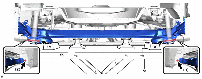
*a
Engine Lifter
*b
Wooden Block
*c
Attachment
-
-
CAUTION:Make sure to secure the rear axle beam assembly to prevent it from dropping.
Remove the 2 bolts (A) and 2 nuts while holding the 2 nuts and separate the rear axle beam assembly from the rear shock absorber assemblies LH and RH.
Note:Because the nuts have their own stoppers, do not turn the nuts. Loosen the bolts with the nuts secured.
Remove the 2 bolts (B) and rear axle beam assembly.
REMOVE REAR AXLE CARRIER BUSHING LH
-
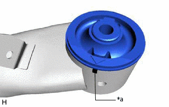
*a
Matchmark
When reusing the rear axle beam assembly:
Put a matchmark on the rear axle beam assembly so that it is aligned with the arrow mark on the rear axle carrier bushing LH.
-
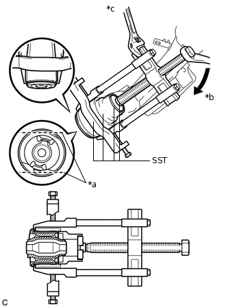
*a
Bend Portion
*b
Turn
*c
Hold
Using a chisel and hammer, bend the 2 ribs on the rear axle carrier bushing LH.
Note:When removing the rear axle carrier bushing, do not erase the matchmark on the rear axle beam assembly.
Using SST, remove the rear axle carrier bushing LH from the rear axle beam assembly.
09710-26011
09710-05061
09950-40011
09951-04020
09952-04010
09953-04030
09954-04020
09955-04051
09957-04010
09958-04011
09950-60010
09951-00530
Note:Apply grease to the threads and tip of the SST center bolt before use.
-
REMOVE REAR AXLE CARRIER BUSHING RH
Tip:Perform the same procedure as for the LH side.