INTAKE MANIFOLD INSTALLATION
PROCEDURE
INSTALL NO. 1 INTAKE MANIFOLD TO HEAD GASKET
Install a new No. 1 intake manifold to head gasket to the intake manifold.
INSTALL INTAKE MANIFOLD
-
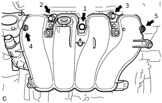
Install the intake manifold with the 3 bolts and 2 nuts in the order shown in the illustration.
24 N*m
245 kgf*cm
18 ft.*lbf
Connect the fuel vapor feed hose to the intake manifold.
Connect the ventilation hose to the intake manifold, and slide the clip to secure it.
-
CONNECT UNION TO CONNECTOR TUBE HOSE (for LHD)
CONNECT CHECK VALVE TO BRAKE BOOSTER HOSE (for RHD)
INSTALL VACUUM SENSOR (MANIFOLD ABSOLUTE PRESSURE SENSOR)
Install the vacuum sensor (manifold absolute pressure sensor) to the intake manifold with the bolt.
5.0 N*m
51 kgf*cm
44 in.*lbf
Connect the vacuum hose.
Install the bracket with the bolt and connect the 2 clamps and connector to the intake manifold.
8.0 N*m
82 kgf*cm
71 in.*lbf
INSTALL NO. 1 EGR PIPE
-
Install 2 new EGR pipe gaskets.
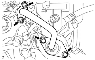
Install the No. 1 EGR pipe with the 2 bolts and 2 nuts.
10 N*m
102 kgf*cm
7 ft.*lbf
-
INSTALL NO. 2 HEATER BRACKET SUB-ASSEMBLY
-
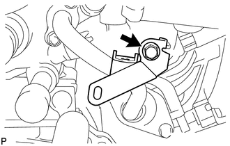
Install the No. 2 heater bracket sub-assembly with the bolt.
7.5 N*m
76 kgf*cm
66 in.*lbf
-
CONNECT HEATER WATER INLET HOSE A
CONNECT HEATER WATER OUTLET HOSE A
INSTALL THROTTLE BODY WITH MOTOR ASSEMBLY
INSTALL OUTER COWL TOP PANEL (for LHD)
for Sedan:
for Hatchback, Wagon:
INSTALL OUTER COWL TOP PANEL (for RHD)
for Sedan:
for Hatchback, Wagon:
INSTALL NO. 2 HEATER AIR DUCT SPLASH SHIELD SEAL (for LHD)
for Sedan:
for Hatchback, Wagon:
INSTALL NO. 2 HEATER AIR DUCT SPLASH SHIELD SEAL (for RHD)
for Sedan:
for Hatchback, Wagon:
INSTALL WATER GUARD PLATE LH (for LHD)
for Sedan:
for Hatchback, Wagon:
INSTALL WATER GUARD PLATE LH (for RHD)
for Sedan:
for Hatchback, Wagon:
INSTALL WINDSHIELD WIPER MOTOR AND LINK ASSEMBLY