UPPER INSTRUMENT PANEL REMOVAL
PROCEDURE
-
PRECAUTION
Note
After turning the power switch off, waiting time may be required before disconnecting the cable from the negative (-) auxiliary battery terminal. Therefore, make sure to read the disconnecting the cable from the negative (-) auxiliary battery terminal notices before proceeding with work Click here.
-
REMOVE DECK BOARD ASSEMBLY
-
REMOVE NO. 1 DECK BOARD
-
REMOVE NO. 2 DECK BOARD
-
REMOVE REAR DECK FLOOR BOX
-
REMOVE DECK FLOOR BOX RH
-
DISCONNECT CABLE FROM NEGATIVE AUXILIARY BATTERY TERMINAL
CAUTION:
Wait at least 90 seconds after disconnecting the cable from the negative (-) auxiliary battery terminal to disable the SRS system.
Note
When disconnecting the cable, some systems need to be initialized after the cable is reconnected Click here.
-
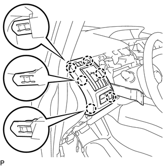
REMOVE INTEGRATION CONTROL AND PANEL
-
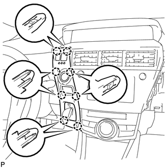
Disengage the 8 claws.
-
Disconnect each connector and remove the integration control and panel.
-
-
REMOVE UPPER INSTRUMENT PANEL FINISH PANEL
-
Disengage the 2 claws and clip and remove the upper instrument panel finish panel.
-
-
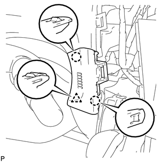
REMOVE LOWER INSTRUMENT PANEL FINISH PANEL ASSEMBLY
-
Disengage the 8 claws and clip.
-
Disconnect each connector and remove the lower instrument panel finish panel assembly.
-
-
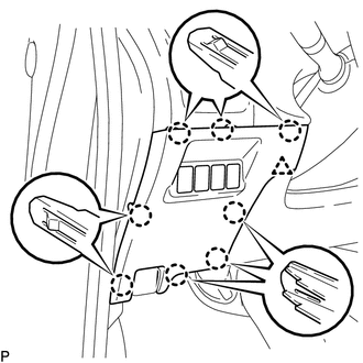
REMOVE UPPER INSTRUMENT PANEL FINISH PANEL SUB-ASSEMBLY
-
Using a moulding remover, disengage the 8 claws and remove the upper instrument panel finish panel sub-assembly.
-
-
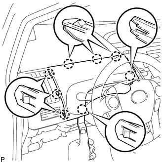
REMOVE NO. 1 INSTRUMENT PANEL REGISTER ASSEMBLY
-
Using a moulding remover, disengage the 6 claws and remove the No. 1 instrument panel register assembly.
-
w/ headup display:
-
Disconnect the connector.
-
-
-
DISCONNECT FRONT DOOR OPENING TRIM WEATHERSTRIP LH
-
Disconnect the front door opening trim weatherstrip LH.
-
-
REMOVE INSTRUMENT PANEL FINISH PANEL END LH
-
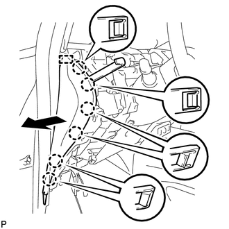
Using a moulding remover, disengage the 6 claws and guide.
-
Disengage the guide and remove the instrument panel finish panel end LH as shown in the illustration.
-
-
REMOVE FRONT PILLAR GARNISH LH
-
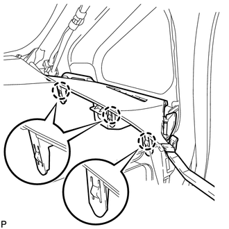
REMOVE LOWER FRONT PILLAR GARNISH LH
-
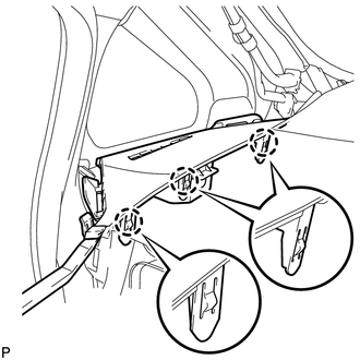
Using a moulding remover, disengage the 3 claws and remove the lower front pillar garnish LH.
-
-
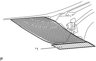
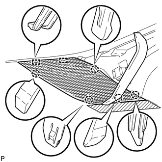
REMOVE NO. 1 INSTRUMENT PANEL SPEAKER PANEL SUB-ASSEMBLY
-
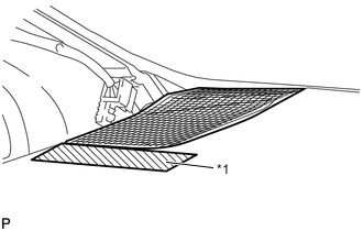
Text in Illustration *1 Protective Tape Apply protective tape to the areas shown in the illustration.
-
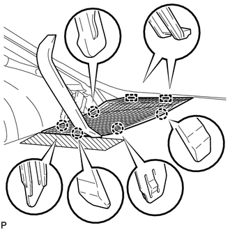
Using a moulding remover, disengage the 5 claws.
-
Disengage the 2 guides and remove the No. 1 instrument panel speaker panel sub-assembly.
-
-
REMOVE FRONT NO. 2 SPEAKER ASSEMBLY
-
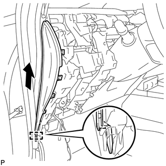
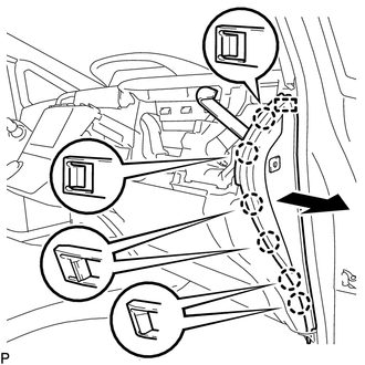
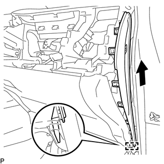
REMOVE INSTRUMENT PANEL BOX ASSEMBLY
-
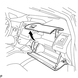
Open the instrument panel box and glove compartment door.
-
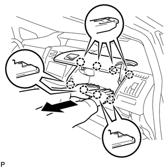
Pull the instrument panel box assembly in the direction indicated by the arrow to disengage the 8 claws as shown in the illustration.
-
Close the glove compartment door.
-
-
REMOVE NO. 2 INSTRUMENT PANEL REGISTER ASSEMBLY
-
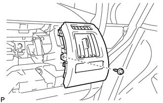
Remove the screw <C>.
-
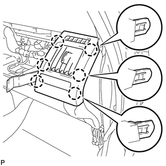
Using a moulding remover, disengage the 6 claws and remove the No. 2 instrument panel register assembly.
-
-
REMOVE INSTRUMENT PANEL CUP HOLDER
-
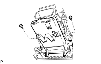
Remove the 2 screws <E> and instrument panel cup holder.
-
-
DISCONNECT FRONT DOOR OPENING TRIM WEATHERSTRIP RH
Tech Tips
Use the same procedure as for the LH side.
-
REMOVE INSTRUMENT PANEL FINISH PANEL END RH
-
Using a molding remover, disengage the 6 claws and guide.
-
Disengage the guide as shown in the illustration.
-
Disconnect the connector to remove the instrument panel finish panel end RH.
-
-
REMOVE FRONT PILLAR GARNISH RH
Tech Tips
Use the same procedure as for the LH side Click here.
-
REMOVE LOWER FRONT PILLAR GARNISH RH
-
Using a moulding remover, disengage the 3 claws and remove the lower front pillar garnish RH.
-
-
REMOVE NO. 2 INSTRUMENT PANEL SPEAKER PANEL SUB-ASSEMBLY
-
Text in Illustration *1 Protective Tape Apply protective tape to the areas shown in the illustration.
-
Using a moulding remover, disengage the 5 claws.
-
Disengage the 2 guides and remove the No. 2 instrument panel speaker panel sub-assembly.
-
-
REMOVE FRONT NO. 2 SPEAKER ASSEMBLY
Tech Tips
Use the same procedure as for the LH side Click here.
-
REMOVE CENTER INSTRUMENT PANEL REGISTER ASSEMBLY
-
Disengage the 8 claws and remove the center instrument panel register assembly.
-
-
REMOVE LOWER CENTER INSTRUMENT CLUSTER FINISH PANEL SUB-ASSEMBLY
-
Disengage the 2 claws and remove the lower center instrument cluster finish panel sub-assembly as shown in the illustration.
-
-
REMOVE NO. 2 HEATER TO REGISTER DUCT SUB-ASSEMBLY
-
Remove the 2 clips.
-
Disengage the 2 guides and remove the No. 2 heater to register duct sub-assembly.
-
-
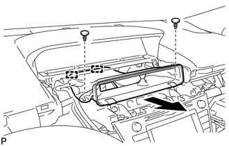
REMOVE INSTRUMENT CLUSTER FINISH PANEL SUB-ASSEMBLY
-
Remove the 2 screws <D> and 3 clips.
-
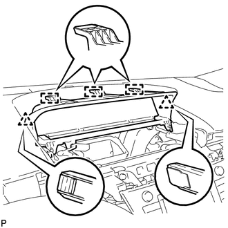
Disengage the 2 clips and 3 guides and remove the instrument cluster finish panel sub-assembly.
-
-
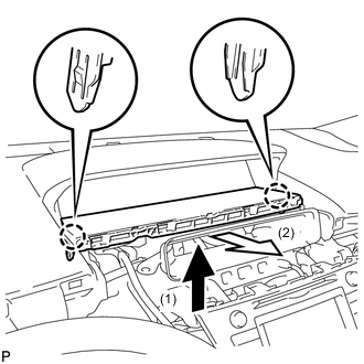
REMOVE INSTRUMENT CLUSTER FINISH PANEL END (w/ Headup Display)
-
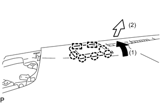
Pull the instrument cluster finish panel end in the direction indicated by the arrow (1) to disengage the 5 claws.
-
Pull the instrument cluster finish panel end in the direction indicated by the arrow (2) to disengage the 2 guides and remove the instrument cluster finish panel end.
-
-
DISCONNECT NO. 3 INSTRUMENT PANEL WIRE
-
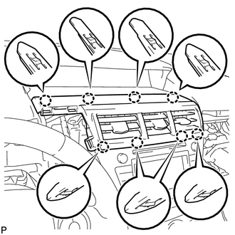
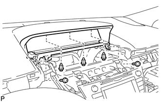
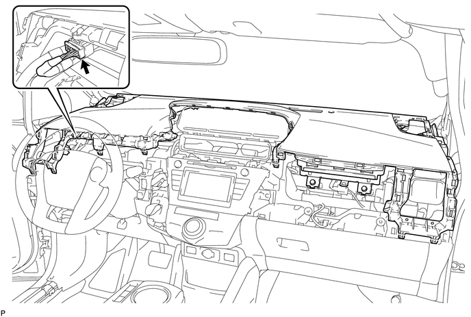
REMOVE UPPER INSTRUMENT PANEL ASSEMBLY
-
Disconnect the connector.
-
Remove the 2 bolts <A> and 2 passenger airbag bolts <B>.
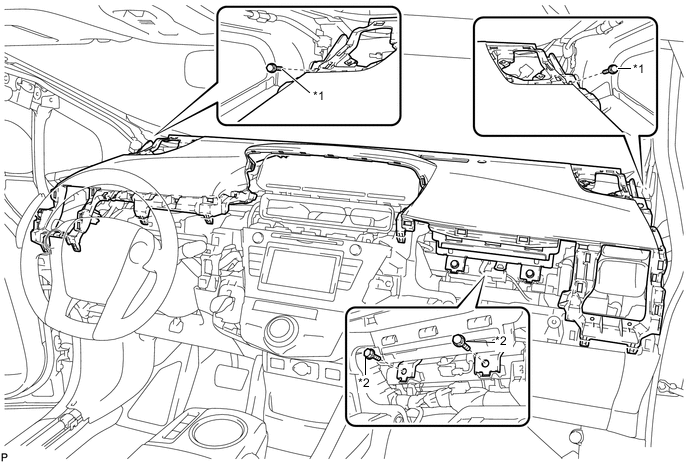
Text in Illustration *1 Bolt <A> *2 Passenger Airbag Bolt <B> -
Disengage the 7 claws (A) as shown in the illustration.
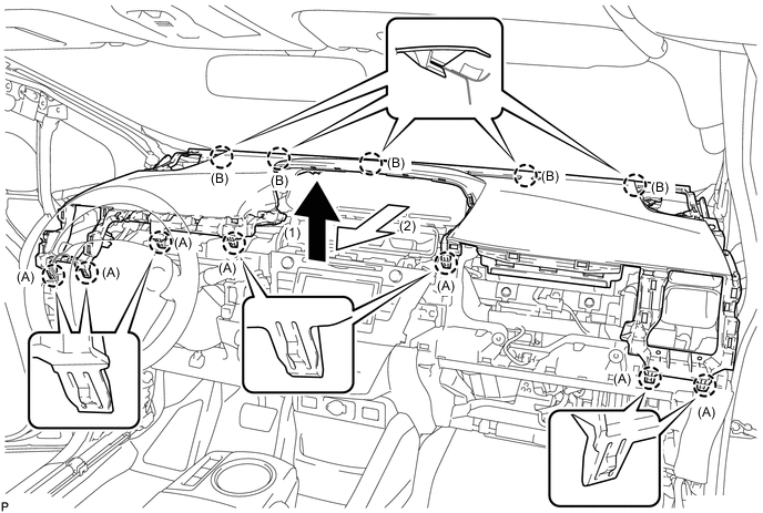
-
Disengage the 5 claws (B) and remove the upper instrument panel assembly as shown in the illustration.
Note
-
Do not damage the upper instrument panel assembly.
-
Do not allow the wire harnesses to interfere with the surrounding parts.
-
-