CAN COMMUNICATION SYSTEM (w/ VSC) TERMINALS OF ECU
Tech Tips
Operating the ignition switch, any switches or any doors triggers related ECU and sensor communication with the CAN, which causes resistance variation.
-
DISCONNECT CABLE FROM NEGATIVE BATTERY TERMINAL
-
Disconnect the cable from the negative (-) battery terminal before measuring the resistances of the main wire and the branch wire.
CAUTION:
Wait at least 90 seconds after disconnecting the cable from the negative (-) battery terminal to disable the SRS system.
Note
-
Before measuring the resistance, leave the vehicle for at least 1 minute and do not operate the ignition switch, any switches or any doors. If doors need to be opened in order to check connectors, open the doors and leave them open.
-
When disconnecting the cable from the negative (-) battery terminal, some systems need to be initialized after the cable is reconnected Click here.
-
-
-
JUNCTION CONNECTOR
-
NO. 1 JUNCTION CONNECTOR
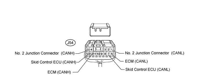
No. 1 Junction Connector Wiring Color Connect to J54-4 (CANH) B No. 2 junction connector J54-1 (CANL) W J54-12 (CANH) B ECM J54-6 (CANL) W J54-13 (CANH) R Skid control ECU J54-7 (CANL) W -
NO. 2 JUNCTION CONNECTOR
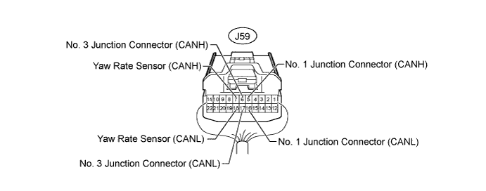
No. 2 Junction Connector Wiring Color Connect to J59-5 (CANH) B No. 1 junction connector J59-16 (CANL) W J59-6 (CANH) B No. 3 junction connector J59-17 (CANL) W J59-7 (CANH) R Yaw rate sensor J59-18 (CANL) W -
NO. 3 JUNCTION CONNECTOR
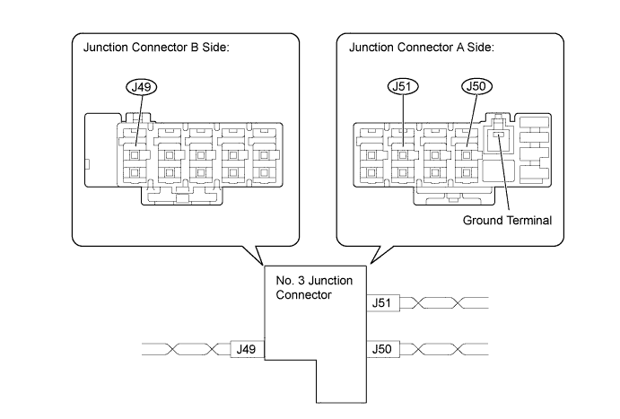
Wiring Color Junction Connector A Side Color (CANH Side) Color (CANL Side) No. 2 junction connector and ECM (J50) B W Steering angle sensor (J51) W R Wiring Color Junction Connector B Side Color (CANH Side) Color (CANL Side) DLC3 (J49) W R
-
-
TERMINALS OF CONNECTORS FOR JUNCTION CONNECTOR
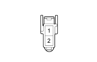
Terminal No. Symbol 1 CANL 2 CANH -
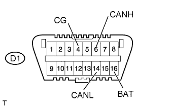
CHECK DLC3
-
Disconnect the cable from the negative (-) battery terminal before measuring the resistances of the main wire and the branch wire.
-
Measure the resistance according to the value(s) in the table below.
Terminal No. (Symbols) Wiring Color Switch Condition Specified Condition D1-6 (CANH) - D1-14 (CANL) W - R Ignition switch off 54 to 69 Ω D1-6 (CANH) - D1-4 (CG) W - G Ignition switch off 200 Ω or higher D1-14 (CANL) - D1-4 (CG) R - G Ignition switch off 200 Ω or higher D1-6 (CANH) - D1-16 (BAT) W - G Ignition switch off 6 kΩ or higher D1-14 (CANL) - D1-16 (BAT) R - G Ignition switch off 6 kΩ or higher
-
-
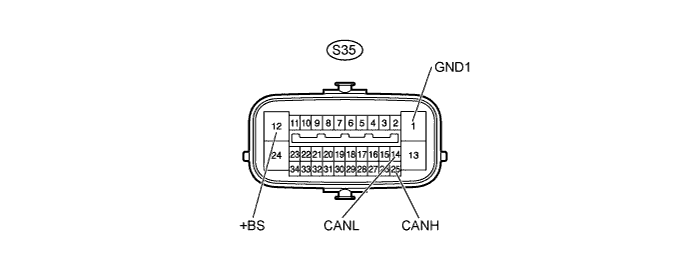
CHECK SKID CONTROL ECU
-
Disconnect the S35 ECU connector.
-
Measure the resistance according to the value(s) in the table below.
Terminal No. (Symbols) Wiring Color Switch Condition Specified Condition S35-25 (CANH) - S35-14 (CANL) B - W Ignition switch off 54 to 69 Ω S35-25 (CANH) - S35-1 (GND1) B - W-B Ignition switch off 200 Ω or higher S35-14 (CANL) - S35-1 (GND1) W - W-B Ignition switch off 200 Ω or higher S35-25 (CANH) - S35-12 (+BS) B - W-R Ignition switch off 6 kΩ or higher S35-14 (CANL) - S35-12 (+BS) W - W-R Ignition switch off 6 kΩ or higher
-
-
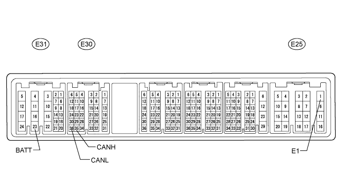
CHECK ECM (for 1KD-FTV, 2KD-FTV [w/ DPF])
-
Disconnect the E25, E30 and E31 ECM connectors.
-
Measure the resistance according to the value(s) in the table below.
Terminal No. (Symbols) Wiring Color Switch Condition Specified Condition E30-35 (CANH) - E30-36 (CANL) B - W Ignition switch off 108 to 132 Ω E30-35 (CANH) - E25-1 (E1) B - BR Ignition switch off 200 Ω or higher E30-36 (CANL) - E25-1 (E1) W - BR Ignition switch off 200 Ω or higher E30-35 (CANH) - E31-23 (BATT) B - L Ignition switch off 6 kΩ or higher E30-36 (CANL) - E31-23 (BATT) W - L Ignition switch off 6 kΩ or higher
-
-
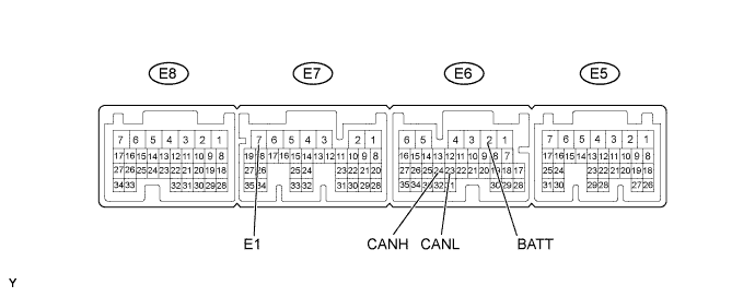
CHECK ECM (for 1KD-FTV, 2KD-FTV [w/o DPF])
-
Disconnect the E6 and E7 ECM connectors.
-
Measure the resistance according to the value(s) in the table below.
Terminal No. (Symbols) Wiring Color Switch Condition Specified Condition E6-24 (CANH) - E6-23 (CANL) B - W Ignition switch off 108 to 132 Ω E6-24 (CANH) - E7-7 (E1) B - BR Ignition switch off 200 Ω or higher E6-23 (CANL) - E7-7 (E1) W - BR Ignition switch off 200 Ω or higher E6-24 (CANH) - E6-2 (BATT) B - L Ignition switch off 6 kΩ or higher E6-23 (CANL) - E6-2 (BATT) W - L Ignition switch off 6 kΩ or higher
-
-
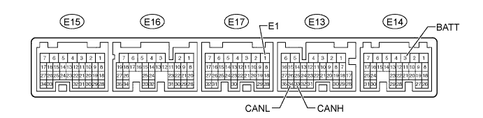
CHECK ECM (for 1GR-FE)
-
Disconnect the E13, E14 and E17 ECM connectors.
-
Measure the resistance according to the value(s) in the table below.
Terminal No. (Symbols) Wiring Color Switch Condition Specified Condition E13-33 (CANH) - E13-34 (CANL) B - W Ignition switch off 108 to 132 Ω E13-33 (CANH) - E17-1 (E1) B - BR Ignition switch off 200 Ω or higher E13-34 (CANL) - E17-1 (E1) W - BR Ignition switch off 200 Ω or higher E13-33 (CANH) - E14-3 (BATT) B - L Ignition switch off 6 kΩ or higher E13-34 (CANL) - E14-3 (BATT) W - L Ignition switch off 6 kΩ or higher
-
-
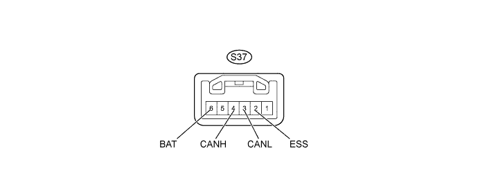
CHECK STEERING ANGLE SENSOR
-
Disconnect the S37 sensor connector.
-
Measure the resistance according to the value(s) in the table below.
Terminal No. (Symbols) Wiring Color Switch Condition Specified Condition S37-4 (CANH) - S37-3 (CANL) W - R Ignition switch off 54 to 69 Ω S37-4 (CANH) - S37-2 (ESS) W - W-B Ignition switch off 200 Ω or higher S37-3 (CANL) - S37-2 (ESS) R - W-B Ignition switch off 200 Ω or higher S37-4 (CANH) - S37-6 (BAT) W - B Ignition switch off 6 kΩ or higher S37-3 (CANL) - S37-6 (BAT) R - B Ignition switch off 6 kΩ or higher
-
-
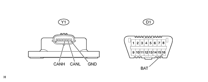
CHECK YAW RATE SENSOR
-
Disconnect the Y1 sensor connector.
-
Measure the resistance according to the value(s) in the table below.
Terminal No. (Symbols) Wiring Color Switch Condition Specified Condition Y1-3 (CANH) - Y1-2 (CANL) B - W Ignition switch off 54 to 69 Ω Y1-3 (CANH) - Y1-1 (GND) B - W-B Ignition switch off 200 Ω or higher Y1-2 (CANL) - Y1-1 (GND) W - W-B Ignition switch off 200 Ω or higher Y1-3 (CANH) - D1-16 (BAT) B - G Ignition switch off 6 kΩ or higher Y1-2 (CANL) - D1-16 (BAT) W - G Ignition switch off 6 kΩ or higher
-