ROOF HEADLINING(for 5 Door) INSTALLATION
PROCEDURE
INSTALL ROOF HEADLINING ASSEMBLY (for Normal Roof)
Gently remove any remaining adhesive from the roof panel.
Tip:It is not necessary to remove the adhesive completely.
Apply adhesive (Henkel Terostat 8595N/MT) to a new roof headlining assembly.
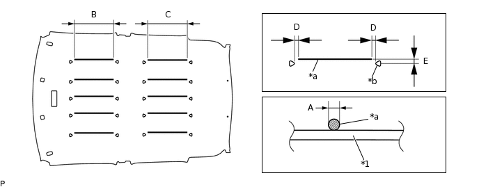
*1
Roof Headlining Assembly
-
-
*a
Adhesive
*b
Marking
Table 1. Specification Area
Measurement
A
Diameter 6 to 8 mm (0.236 to 0.315 in.)
B
330 mm (1.08 ft.)
C
335 mm (1.10 ft.)
D
17 mm (0.669 in.)
E
20 to 30 mm (0.787 to 1.18 in.)
Note:Apply adhesive 20 to 30 mm (0.787 to 1.18 in.) from the markings on the roof headlining assembly.
Do not apply too much adhesive.
-
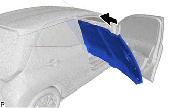
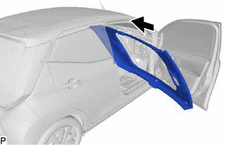
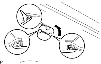
Put the roof headlining assembly into the vehicle through the front passenger door as shown in the illustration.
Note:Do not damage the roof headlining assembly or vehicle interior.
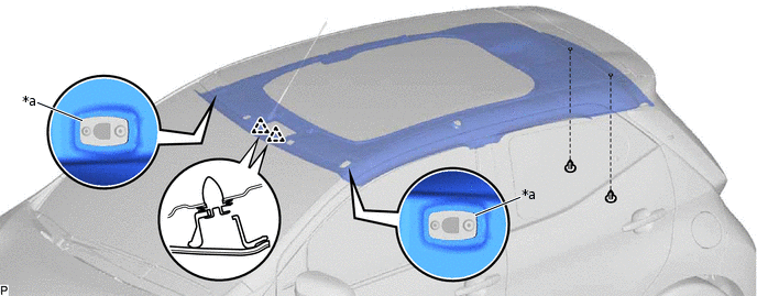
Push the roof headlining assembly up to the roof panel until the distance between the roof panel and the back surface of the roof headlining assembly is less than 4 mm (0.157 in.) at all 18 points shown in the illustration.
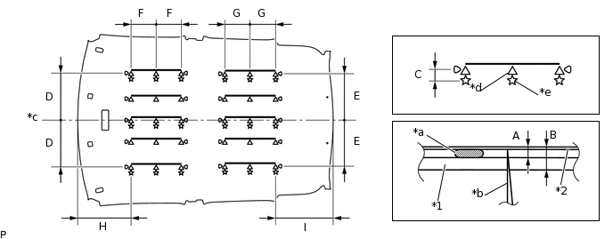
*1
Roof Headlining Assembly
*2
Roof Panel
*a
Adhesive
*b
Needle
*c
Center
*d
Push Up Area
*e
Insert Point
-
-
Note:Be sure to press the roof headlining assembly onto the roof panel with clean hands.
Gently and uniformly press the roof headlining assembly as pressing it at a single point may damage it.
Table 2. Specification Area
Measurement
A
4 mm or less (0.157 in. or less)
B
10 mm or less (0.394 in. or less)
C
19 mm (0.748 in.)
D
306 mm (1.00 ft.)
E
301 mm (11.9 in.)
F
165 mm (6.50 in.)
G
167 mm (6.57 in.)
H
353 mm (1.16 ft.)
I
377 mm (1.24 ft.)
Insert a clean needle into the 18 points shown in the illustration from the roof headlining assembly side, and press the roof headlining assembly until the distance between the roof panel and roof headlining assembly outer surface is less than 10 mm (0.394 in.).
Note:Do not stick the needle into areas where adhesive is applied, as the adhesive may seep onto the roof headlining assembly.
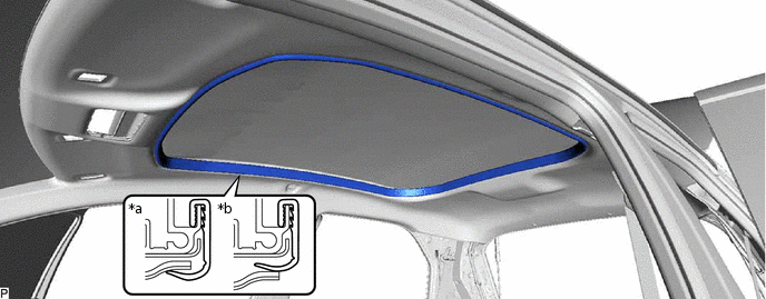
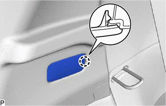
Install the 2 clips.
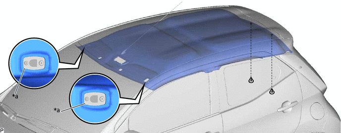
*a
Visor Bracket Hole
-
-
Tip:Make sure that the visor bracket hole of the roof headlining assembly is positioned as shown in the illustration.
TEMPORARILY INSTALL ROOF HEADLINING ASSEMBLY (for Canvas Top)
-
Put the roof headlining assembly into the vehicle through the front passenger door as shown in the illustration.
Note:Do not damage the roof headlining assembly or vehicle interior.
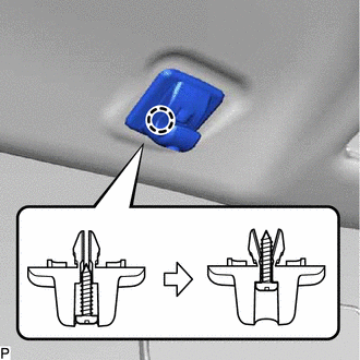
Engage the 2 clips.
*a
Visor Bracket Hole
-
-
Install the 2 clips.
Tip:Make sure that the visor bracket hole of the roof headlining assembly is positioned as shown in the illustration.
-
INSTALL VISOR HOLDER LH
-
Engage the claw.
Install the visor holder LH with the screw as shown in the illustration.
-
INSTALL VISOR HOLDER RH
Tip:Use the same procedure as for the LH side.
INSTALL VISOR ASSEMBLY LH
Install the visor assembly LH with the 2 screws.
INSTALL VISOR ASSEMBLY RH
Tip:Use the same procedure as for the LH side.
INSTALL ROOF HEADLINING ASSEMBLY (for Canvas Top)
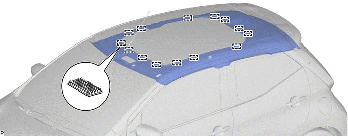
Engage the 14 fasteners to install the roof headlining assembly.
INSTALL ROOF HEADLINING ASSEMBLY HOLE PLUG (for Canvas Top)
Tip:Use the same procedure for the RH side and LH side.
Install a new roof headlining assembly hole plug with the bolt.
-
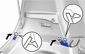
Engage the 3 claws as shown in the illustration.
INSPECT NO. 2 SLIDING ROOF OPENING TRIM MOULDING (for Canvas Top)
Check that the No. 2 sliding roof opening trim moulding is properly installed as shown in the illustration.
*a
Correct
*b
Incorrect
INSTALL MAP LIGHT ASSEMBLY (for Normal Roof)
INSTALL MAP LIGHT ASSEMBLY (for Canvas Top)
INSTALL LOWER INSTRUMENT PANEL
INSTALL INNER ROOF SIDE GARNISH LH
-
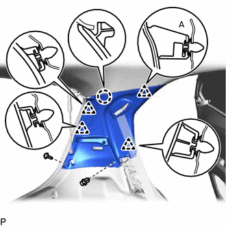
w/ Curtain Shield Airbag:
Install a new clip (A) to the inner roof side garnish LH.
Pass the floor anchor of the No. 1 rear seat outer belt assembly LH through the inner roof side garnish LH.
Engage the claw and 4 clips to install the inner roof side garnish LH.
Install the screw and clip.
-
Engage the 3 claws as shown in the illustration.
-
INSTALL INNER ROOF SIDE GARNISH COVER LH (w/o Luggage Compartment Room Light)
Connect the connector.
-
Engage the claw to install the inner roof side garnish cover LH.
INSTALL NO. 1 LUGGAGE COMPARTMENT LIGHT ASSEMBLY (w/ Luggage Compartment Room Light)
INSTALL UPPER CENTER PILLAR GARNISH LH
w/ Curtain Shield Airbag:
Install a new clip to the upper center pillar garnish LH.
Pass the floor anchor of the front seat outer belt assembly LH through the upper center pillar garnish LH.
Engage the clip and claw to install the upper center pillar garnish LH.
INSTALL LOWER CENTER PILLAR GARNISH LH
Engage the 5 claws and 2 clips to install the lower center pillar garnish LH.
INSTALL REAR SEAT SIDE GARNISH LH
Engage the 5 claws and clip to install the rear seat side garnish LH.
Install the clip.
CONNECT NO. 1 REAR SEAT OUTER BELT ASSEMBLY LH
CONNECT FRONT SEAT OUTER BELT ASSEMBLY LH
INSTALL INNER ROOF SIDE GARNISH RH
Tip:Use the same procedure as for the LH side.
INSTALL UPPER CENTER PILLAR GARNISH RH
Tip:Use the same procedure as for the LH side.
INSTALL LOWER CENTER PILLAR GARNISH RH
Tip:Use the same procedure as for the LH side.
INSTALL REAR SEAT SIDE GARNISH RH
Tip:Use the same procedure as for the LH side.
CONNECT NO. 1 REAR SEAT OUTER BELT ASSEMBLY RH
Tip:Use the same procedure as for the LH side.
CONNECT FRONT SEAT OUTER BELT ASSEMBLY RH
Tip:Use the same procedure as for the LH side.
INSTALL REAR DOOR OPENING TRIM WEATHERSTRIP LH
-
*a
Alignment Mark (White)

Flange Position
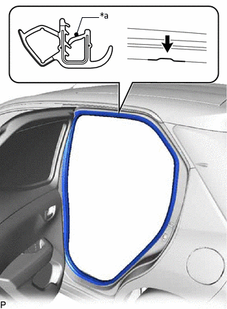
Align the alignment mark (white) on a new rear door opening trim weatherstrip LH with the flange on the vehicle body indicated by the arrow in the illustration, and install it.
Note:After installation, check that the corners fit correctly.
-
INSTALL FRONT PILLAR GARNISH LH
-
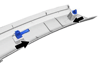
w/ Curtain Shield Airbag:
Install 2 new clips to the front pillar garnish LH as shown in the illustration.
Remove the protective cover.
-
Push the front pillar garnish LH as shown in the illustration to engage the 2 guides.
-
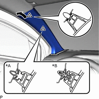
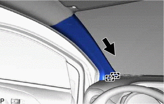
*A
w/o Curtain Shield Airbag
*B
w/ Curtain Shield Airbag
Engage the 2 clips to install the front pillar garnish LH as shown in the illustration.
-
INSTALL FRONT DOOR OPENING TRIM WEATHERSTRIP LH
-
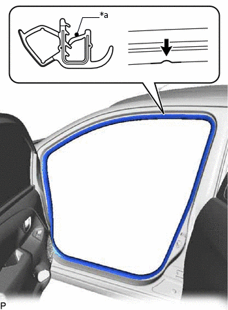
*a
Alignment Mark (White)
Flange Position
Align the alignment mark (white) on a new front door opening trim weatherstrip LH with the flange on the vehicle body indicated by the arrow in the illustration, and install it.
Note:After installation, check that the corners fit correctly.
-
INSTALL COWL SIDE TRIM SUB-ASSEMBLY LH
INSTALL REAR DOOR OPENING TRIM WEATHERSTRIP RH
-
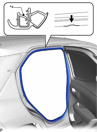
*a
Alignment Mark (Green)
Flange Position
Align the alignment mark (green) on a new rear door opening trim weatherstrip RH with the flange on the vehicle body indicated by the arrow in the illustration, and install it.
Note:After installation, check that the corners fit correctly.
-
INSTALL FRONT PILLAR GARNISH RH
Tip:Use the same procedure as for the LH side.
INSTALL FRONT DOOR OPENING TRIM WEATHERSTRIP RH
-
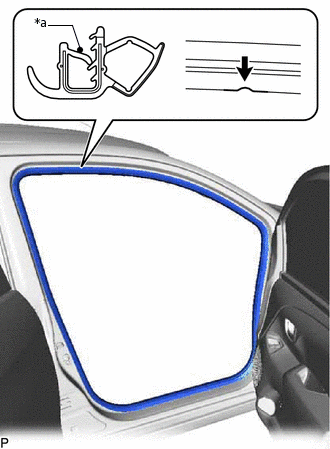
*a
Alignment Mark (Blue)
Flange Position
Align the alignment mark (blue) on a new front door opening trim weatherstrip RH with the flange on the vehicle body indicated by the arrow in the illustration, and install it.
Note:After installation, check that the corners fit correctly.
-
INSTALL COWL SIDE TRIM BOARD RH
INSTALL REAR SEAT ASSEMBLY (for Separate Seat Type)
INSTALL REAR SEAT ASSEMBLY (for Bench Seat Type)
INSTALL FRONT SEAT ASSEMBLY LH
INSTALL FRONT SEAT ASSEMBLY RH
Tip:Use the same procedure as for the LH side.
INSTALL REAR FLOOR MAT ASSEMBLY
Install the rear floor mat assembly.
INSTALL PACKAGE TRAY TRIM PANEL ASSEMBLY (w/ Package Tray Trim)
Install the package tray trim panel assembly.