METER / GAUGE SYSTEM GENERAL GENERAL
OUTLINE
The combination meter assembly is mounted on the steering column. Thus the position of the combination meter assembly adjusts unison with the adjustment of the steering column. This contributes to enhancing the visibility of the combination meter assembly.
A segment Liquid Crystal Display (LCD) is used for the multi-information display.
3 types of segment LCD displays are provided depending on the engine or transaxle.
The combination meter assembly has a forward switch knob and back switch knob to change multi-information display contents (forward or backward). This makes it less troublesome for the driver to change the multi-information display contents.
A segment type tachometer is available as optional equipment.
The combination meter assembly has a built-in meter ECU and buzzer.
Figure 1. Models with 1KR-FE Engine and Manual Transaxle 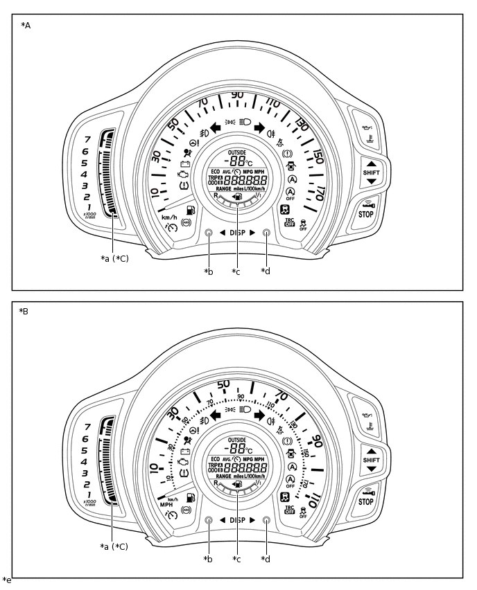
*A
Models with km/h Indication Speedometer
*B
Models with km/h and MPH Indication Speedometer
*C
Models with Tachometer
-
-
*a
Tachometer
*b
Back Switch Knob
*c
Multi-information Display
*d
Forward Switch Knob
*e
The illustrations shown are examples only.
-
-
Figure 2. Models with 1KR-FE Engine and Multi-mode Manual Transaxle 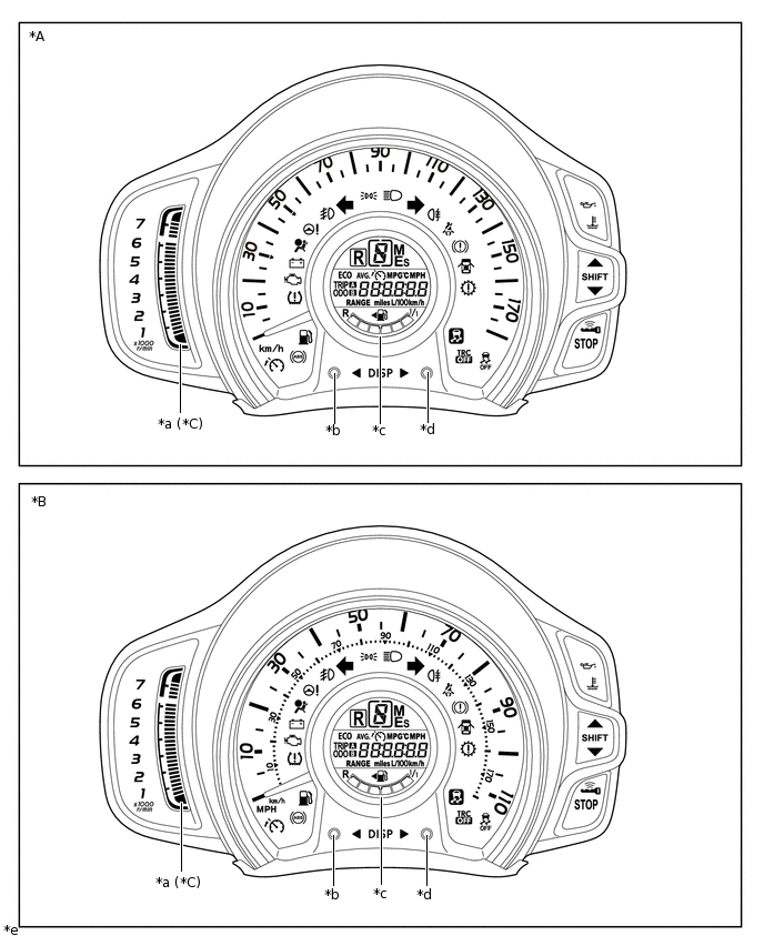
*A
Models with km/h Indication Speedometer
*B
Models with km/h and MPH Indication Speedometer
*C
Models with Tachometer
-
-
*a
Tachometer
*b
Back Switch Knob
*c
Multi-information Display
*d
Forward Switch Knob
*e
The illustrations shown are examples only.
-
-
Figure 3. Models with 1PP Engine 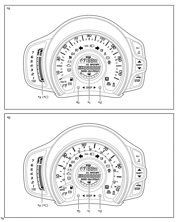
*A
Models with km/h Indication Speedometer
*B
Models with km/h and MPH Indication Speedometer
*C
Models with Tachometer
-
-
*a
Tachometer
*b
Back Switch Knob
*c
Multi-information Display
*d
Forward Switch Knob
*e
The illustrations shown are examples only.
-
-
MAIN FEATURES
Multi-information Display
The segment LCD type multi-information display shows the following information:
Mode
Outline
Outside Temperature
The outside temperature is displayed.
When the outside temperature drops below 3°C (37°F), an outside temperature display flashes 10 times to warn the driver to drive with caution due to the possibility of icy road conditions.
Shift Position Indicator*1
The current shift position is displayed.
Fuel Level Gauge
The fuel level is displayed using 6 segments.
The vehicle side location of the fuel filler flap is displayed.
Speed Limiter Control System Information*2
The following information of the speed limiter control system can be displayed.
System standby/ON state
Set limit speed
Cruise Information
The following information items can be displayed. The item shown can be switched by pressing the forward and back switch knobs.
Odometer
Trip Meter A
Trip Meter B
Stop and Start Operation Time after Engine Start-up*3
Total Stop and Start Operation Time*3
Outside Temperature*4
Current Fuel Consumption
Total Average Fuel Consumption
Cruising Range
Average Vehicle Speed
Meter Panel Luminance Adjustment Mode*5
Interruption Display
When the conditions are met, the following information can be displayed.
Speed Limiter Control System Set Speed*6
Icy Road Condition*4
Stop and Start Operation Time after Engine Start-up*3
Tip:When any of the above information is being displayed, the previous screen can be shown by pressing either of the switch knobs.
Meter Panel Luminance Adjustment
Meter panel luminance when the taillights are on can be changed.
Customization*3
The interruption display of the Stop and Start Operation Time after Engine Start-up can be enabled or disabled.
Pressing and holding either of the switch knobs when Stop and Start Operation Time after Engine Start-up is displayed changes the display to the interruption display of the Stop and Start Operation Time after Engine Start-up customization display.
*1: Models with multi-mode manual transaxle
*2: Models with 1PP engine
*3: Models with stop and start system
*4: Except models with 1KR-FE engine and manual transaxle
*5: When the taillights are on
*6: Models with 1KR-FE engine
Tachometer (Models with Tachometer)
The tachometer is displayed in the segment LCD display to the left side of the main speedometer and multi-information display area.
The red zone area is 6251 to 7500 rpm.
PRECAUTION
Ignition Switch Expressions
The type of ignition switch used on this model differs depending on the specifications of the vehicle. The expressions listed in the table below are used in this section.
Expressions
Ignition Switch (Position)
Engine Switch (Condition)
Ignition Switch off
LOCK
Off (LOCK)
Ignition Switch ACC
ACC
On (ACC)
Ignition Switch ON
ON
On (IG)
Engine Start
START
On (Start)