AIR CONDITIONING SYSTEM(for Automatic Air Conditioning System) PTC Heater Circuit
DESCRIPTION
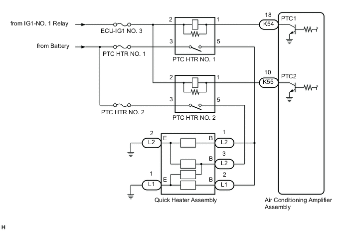
The air conditioning amplifier assembly sends operation signals to the PTC HTR relays when quick heater assembly operation conditions are met. Based on the signals from the air conditioning amplifier assembly, the PTC HTR relays turn on, and power is supplied to the quick heater assembly installed in the air conditioning radiator assembly.
| Symptom | Factor |
|---|---|
| Heating performance is poor when it is cold. |
|
WIRING DIAGRAM
CAUTION / NOTICE / HINT
Note
Inspect the fuses for circuits related to this system before performing the following procedure.
PROCEDURE
-
INSPECT PTC HTR RELAY
-
Inspect the PTC HTR relays.
Result Proceed to OK NG
NG 
REPLACE PTC HTR RELAY
OK 
-
-
CHECK HARNESS AND CONNECTOR (POWER SOURCE - PTC HTR RELAY)
-
Measure the voltage according to the value(s) in the table below.
Standard Voltage PTC HTR NO. 1 Tester Connection Condition Specified Condition 3 (PTC HTR NO. 1 relay) - Body ground Always 11 to 14 V 2 (PTC HTR NO. 1 relay) - Body ground Ignition switch off Below 1 V 2 (PTC HTR NO. 1 relay) - Body ground Ignition switch ON 11 to 14 V PTC HTR NO. 2 Tester Connection Condition Specified Condition 3 (PTC HTR NO. 2 relay) - Body ground Always 11 to 14 V 2 (PTC HTR NO. 2 relay) - Body ground Ignition switch off Below 1 V 2 (PTC HTR NO. 2 relay) - Body ground Ignition switch ON 11 to 14 V Result Proceed to OK NG
NG
REPAIR OR REPLACE HARNESS OR CONNECTOR
OK
-
-
CHECK HARNESS AND CONNECTOR (PTC HTR RELAY - AIR CONDITIONING AMPLIFIER ASSEMBLY)
-
Disconnect the K54 and K55 air conditioning amplifier assembly connectors.
-
Measure the resistance according to the value(s) in the table below.
Standard Resistance PTC HTR NO. 1 Tester Connection Condition Specified Condition 1 (PTC HTR NO. 1 relay) - K54-18 (PTC1) Always Below 1 Ω 1 (PTC HTR NO. 1 relay) or K54-18 (PTC1) - Other terminals and body ground Always 10 kΩ or higher PTC HTR NO. 2 Tester Connection Condition Specified Condition 1 (PTC HTR NO. 2 relay) - K55-10 (PTC2) Always Below 1 Ω 1 (PTC HTR NO. 2 relay) or K55-10 (PTC2) - Other terminals and body ground Always 10 kΩ or higher Result Proceed to OK NG
NG
REPAIR OR REPLACE HARNESS OR CONNECTOR
OK
-
-
CHECK HARNESS AND CONNECTOR (PTC HTR RELAY - QUICK HEATER ASSEMBLY AND BODY GROUND)
-
Disconnect the L1 and L2 quick heater assembly connectors.
-
Measure the resistance according to the value(s) in the table below.
Standard Resistance PTC HTR NO. 1 Tester Connection Condition Specified Condition 5 (PTC HTR NO. 1 relay) - L1-2 (B) Always Below 1 Ω 5 (PTC HTR NO. 1 relay) - L2-1 (B) Always Below 1 Ω 5 (PTC HTR NO. 1 relay) or L1-2 (B) - Other terminals and body ground Always 10 kΩ or higher 5 (PTC HTR NO. 1 relay) or L2-1 (B) - Other terminals and body ground Always 10 kΩ or higher PTC HTR NO. 2 Tester Connection Condition Specified Condition 5 (PTC HTR NO. 2 relay) - L2-3 (B) Always Below 1 Ω 5 (PTC HTR NO. 2 relay) or L2-3 (B) - Other terminals and body ground Always 10 kΩ or higher Result Proceed to OK NG
NG
REPAIR OR REPLACE HARNESS OR CONNECTOR
OK
-
-
INSPECT QUICK HEATER ASSEMBLY
-
Remove the quick heater assembly.
-
Inspect the quick heater assembly.
Result Proceed to OK NG
OK
REPLACE AIR CONDITIONING AMPLIFIER ASSEMBLY Click here
NG
REPLACE QUICK HEATER ASSEMBLY Click here
-