DYNAMIC TORQUE CONTROL AWD SYSTEM, Diagnostic DTC:C120C/79

| DTC Code | DTC Name |
|---|---|
| C120C/79 | Linear Solenoid Power Supply System Malfunction |
DESCRIPTION
This DTC is output by the 4WD ECU assembly if a malfunction occurs in the linear solenoid power supply system.
| DTC No. | Detection Item | DTC Detection Condition | Trouble Area |
|---|---|---|---|
| C120C/79 | Linear Solenoid Power Supply System Malfunction |
|
|
WIRING DIAGRAM
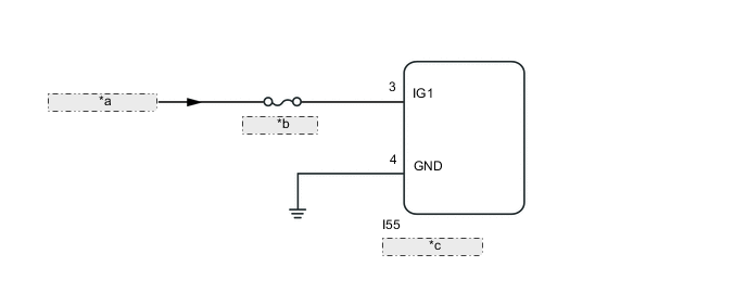
| *a | from IG1 Circuit |
| *b | ECU-IG NO. 6 |
| *c | 4WD ECU Assembly |
CAUTION / NOTICE / HINT
Note
-
Inspect the fuses for circuits related to this system before performing the following inspection procedure.
-
When the 4WD ECU assembly is replaced with a normal one from another vehicle, it is necessary to perform calibration.
PROCEDURE
-
CHECK HARNESS AND CONNECTOR (IG1 TERMINAL)
-
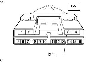
*a Front view of wire harness connector
(to 4WD ECU Assembly)
Disconnect the I55 4WD ECU assembly connector.
-
Turn the engine switch on (IG).
-
Measure the voltage according to the value(s) in the table below.
Standard Voltage Tester Connection Switch Condition Specified Condition I55-3 (IG1) -Body ground Engine switch on (IG) 11 to 14 V Result Proceed to OK NG
NG 
REPAIR OR REPLACE HARNESS OR CONNECTOR
OK 
-
-
CHECK HARNESS AND CONNECTOR (GND TERMINAL)
-
Turn the engine switch off.
-
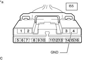
*a Front view of wire harness connector
(to 4WD ECU Assembly)
Measure the resistance according to the value(s) in the table below.
Standard Resistance Tester Connection Condition Specified Condition I55-4 (GND) -Body ground Always Below 1 Ω Result Proceed to OK NG
NG
REPAIR OR REPLACE HARNESS OR CONNECTOR
OK
-
-
RECONFIRM DTC
-
Reconnect the I55 4WD ECU assembly connector.
-
Clear the DTCs.
Chassis > Four Wheel Drive > Clear DTCs -
Turn the engine switch off.
-
Turn the engine switch on (IG).
-
Check that no DTCs other than DTC C120C/79 have been output.
Chassis > Four Wheel Drive > Trouble CodesResult Proceed to DTCs other than C120C/79 are not output DTCs other than C120C/79 are output
DTCs other than C120C/79 are not output
REPLACE 4WD ECU ASSEMBLY for LHD: Click here
REPLACE 4WD ECU ASSEMBLY for RHD: Click hereDTCs other than C120C/79 are output
REPAIR CIRCUIT INDICATED BY OUTPUT CODE Click here
-