AIR SUSPENSION SYSTEM, Diagnostic DTC:C1782/82
| DTC Code | DTC Name |
|---|---|
| C1782/82 | Low Battery Positive Voltage |
DESCRIPTION
DTC No. |
Detection Item |
DTC Detection Condition |
Trouble Area |
Warning Indicate |
|---|---|---|---|---|
C1782/82 |
Low Battery Positive Voltage |
The voltage at terminal IG or B is 10 V or less or 16 V or higher for 0.5 seconds. |
|
Not indicated |
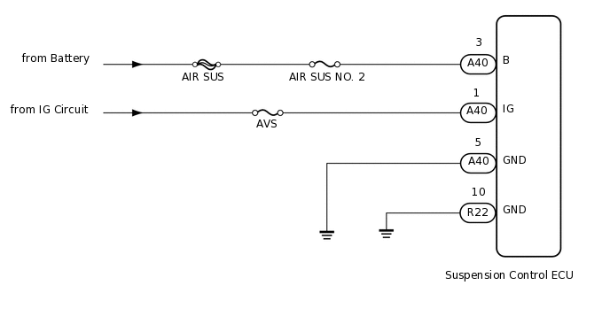
WIRING DIAGRAM
CAUTION / NOTICE / HINT
When replacing the suspension control ECU, perform registration (Click here).
Inspect the fuses for circuits related to this system before performing the following inspection procedure.
PROCEDURE
READ VALUE USING INTELLIGENT TESTER (IG/+B POWER SOURCE VOLTAGE)
Turn the engine switch off.
Connect the intelligent tester to the DLC3.
Turn the engine switch on (IG).
Turn the intelligent tester on.
Enter the following menus: Chassis / Air suspension / Data List.
Chassis > Air suspension > Data List
Tester Display
Measurement Item
Range
Normal Condition
Diagnostic Note
IG Power Source Voltage
Actual ECU power supply voltage
Min.: 0.0 V
Max.: 25.5 V
Engine switch on (IG): 11 to 14 V
-
+B Power Source Voltage
Actual battery supply voltage
Min.: 0.0 V
Max.: 25.5 V
Engine switch on (IG): 11 to 14 V
-
OK
11 to 14 V
Result
Result
Proceed to
NG
A
OK (When troubleshooting according to problem symptoms table)
B
OK (When troubleshooting according to DTC chart)
C
CHECK TERMINAL VOLTAGE (IG, B)
Disconnect the A40 suspension control ECU connector.
-
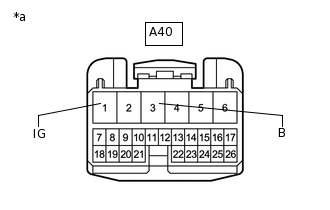
*a
Front view of wire harness connector
(to Suspension Control ECU)
Measure the voltage according to the value(s) in the table below.
Standard Voltage
Tester Connection
Switch Condition
Specified Condition
A40-3 (B) - Body ground
Always
11 to 14 V
A40-1 (IG) - Body ground
Engine switch on (IG)
11 to 14 V
Result
Result
OK
NG
NG REPAIR OR REPLACE HARNESS OR CONNECTOR
CHECK HARNESS AND CONNECTOR (SUSPENSION CONTROL ECU - BODY GROUND)
Disconnect the A40 and R22 suspension control ECU connectors.
Measure the resistance according to the value(s) in the table below.
Standard Resistance
Tester Connection
Condition
Specified Condition
R22-10 (GND) - Body ground
Always
Below 1 Ω
A40-5 (GND) - Body ground
Always
Below 1 Ω
Result
Result
OK
NG
NG REPAIR OR REPLACE HARNESS OR CONNECTOR
CHECK FOR DTC
Clear the DTC.
Chassis > Air suspension > Clear DTCs
Check the DTC.
Chassis > Air suspension > Trouble Codes
Result
Result
Proceed to
DTC is not output
A
DTC is output
B