PROPELLER SHAFT ASSEMBLY (for Super Long Wheelbase) REASSEMBLY

-
INSTALL UNIVERSAL JOINT SPIDER ASSEMBLY
-
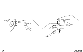
Apply MP grease No.2 to a new spider and bearings.
-
Fit the spider into the flange yoke.
-
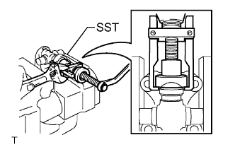
Using SST, install the bearings on the spider.
- SST
- 09332-25010
-
Using SST, adjust both bearings so that the snap ring grooves are at the maximum and equal in width.
-
Install 2 new snap rings with the same thickness which allow 0.05 mm (0.002 in.) or less axial play.
Note
Do not reuse the snap rings.
Thickness of snap ring Parts No. Thickness mm (in.) Mark 90520-25039 2.28 to 2.30 (0.0898 to 0.0906) 1 90520-25040 2.30 to 2.32 (0.0906 to 0.0913) 2 90520-25041 2.32 to 2.34 (0.0913 to 0.0921) - 90520-25042 2.34 to 2.36 (0.0921 to 0.0929) Brown 90520-25043 2.36 to 2.38 (0.0929 to 0.0937) Blue 90520-25044 2.38 to 2.40 (0.0937 to 0.0945) 6 90520-25045 2.40 to 2.42 (0.0945 to 0.0953) 7 90520-25046 2.42 to 2.44 (0.0953 to 0.0961) 8 90520-25047 2.44 to 2.46 (0.0961 to 0.0969) 
90520-25048 2.46 to 2.48 (0.0969 to 0.0976) 10 90520-25049 2.48 to 2.50 (0.0976 to 0.0984) A 90520-25050 2.50 to 2.52 (0.0984 to 0.0992) B 90520-25051 2.52 to 2.54 (0.0992 to 0.1) C 90520-25052 2.54 to 2.56 (0.1 to 0.1008) D 90520-25053 2.56 to 2.58 (0.1008 to 0.1016) E 90520-25054 2.18 to 2.20 (0.0858 to 0.0866) J 90520-25055 2.20 to 2.22 (0.0866 to 0.0874) K 90520-25056 2.22 to 2.24 (0.0874 to 0.0882) F 90520-25057 2.24 to 2.26 (0.0882 to 0.089) G 90520-25058 2.26 to 2.28 (0.089 to 0.0898) H Tech Tips
Snap rings with the same thickness should be used on both ends.
-
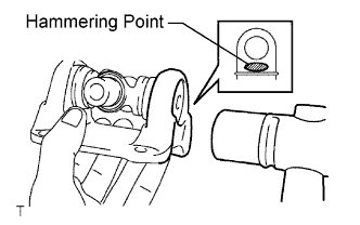
Using a hammer, tap the flange yoke until there is no clearance between the spider bearing outer race and snap ring.
Note
Do not damage the flange yoke.
Tech Tips
Install the spider bearing on the opposite side using the same procedure.
-
Align the matchmarks on the propeller shaft assembly and flange yoke.
-
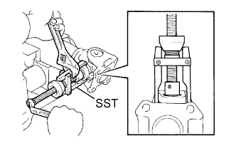
Using SST, adjust both bearings so that the snap ring grooves are at the maximum and equal in width.
- SST
- 09332-25010
-
Install 2 new snap rings with the same thickness which allow 0.05 mm (0.002 in.) or less axial play.
Note
Do not reuse the snap rings.
Thickness of snap ring Parts No. Thickness mm (in.) Mark 90520-25039 2.28 to 2.30 (0.0898 to 0.0906) 1 90520-25040 2.30 to 2.32 (0.0906 to 0.0913) 2 90520-25041 2.32 to 2.34 (0.0913 to 0.0921) - 90520-25042 2.34 to 2.36 (0.0921 to 0.0929) Brown 90520-25043 2.36 to 2.38 (0.0929 to 0.0937) Blue 90520-25044 2.38 to 2.40 (0.0937 to 0.0945) 6 90520-25045 2.40 to 2.42 (0.0945 to 0.0953) 7 90520-25046 2.42 to 2.44 (0.0953 to 0.0961) 8 90520-25047 2.44 to 2.46 (0.0961 to 0.0969) 90520-25048 2.46 to 2.48 (0.0969 to 0.0976) 10 90520-25049 2.48 to 2.50 (0.0976 to 0.0984) A 90520-25050 2.50 to 2.52 (0.0984 to 0.0992) B 90520-25051 2.52 to 2.54 (0.0992 to 0.1) C 90520-25052 2.54 to 2.56 (0.1 to 0.1008) D 90520-25053 2.56 to 2.58 (0.1008 to 0.1016) E 90520-25054 2.18 to 2.20 (0.0858 to 0.0866) J 90520-25055 2.20 to 2.22 (0.0866 to 0.0874) K 90520-25056 2.22 to 2.24 (0.0874 to 0.0882) F 90520-25057 2.24 to 2.26 (0.0882 to 0.089) G 90520-25058 2.26 to 2.28 (0.089 to 0.0898) H Tech Tips
Snap rings with the same thickness should be used on both ends.
-
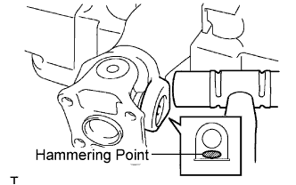
Using a hammer, tap the flange yoke until there is no clearance between the spider bearing outer race and snap ring.
Note
Do not damage the flange yoke.
Tech Tips
Install the spider bearing on the opposite side using the same procedure.
-
-
INSPECT UNIVERSAL JOINT SPIDER ASSEMBLY
-
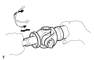
Check that the spider bearing rotates smoothly.
-
Check that there is no play in the spider bearing.
Tech Tips
If necessary, replace the intermediate shaft.
-
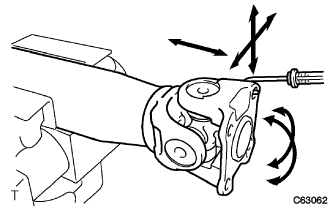
Using a spring tension gauge, hang the hook of the spring tension gauge on the bolt hole of the flange yoke and measure the rotating force.
- Torque:
- 1.1 N*m { 11.2 kgf*cm, 9.68 in.*lbf }
Note
Measurement of rotating force should be done at 2 positions for each universal joint by 90° in opposite directions (flange yoke side and end yoke side). When the rotating force is less than the standard, use a lank thicker retainer ring. When it exceeds the standard, use a thinner one.
-
-
INSTALL CENTER SUPPORT BEARING ASSEMBLY NO.1
-
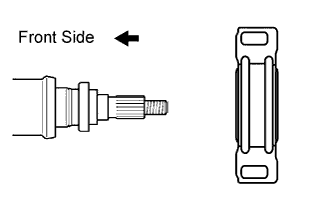
Set the center support bearing assembly No.1 on the intermediate shaft assembly, as shown in the illustration.
Note
Be sure to install the bearing in the correct direction.
-
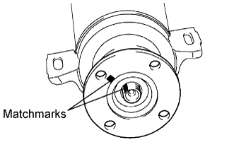
Align the matchmarks on the universal joint flange and intermediate shaft assembly, and place the universal joint flange on the intermediate shaft assembly.
-
Hold the intermediate shaft assembly in a vise between aluminium plates.
Note
Do not overtighten the vise.
-
Install the washer.
-
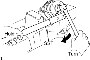
Using SST to hold the universal joint flange, press the center support bearing assembly No.1 into position by tightening a new nut.
- SST
- 09330-00021
- Torque:
- 181 N*m { 1,850 kgf*cm, 134 ft.*lbf }
-
Loosen the nut.
-
Retighten the nut.
- Torque:
- 69 N*m { 700 kgf*cm, 51 ft.*lbf }
-
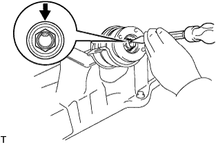
Using a chisel and a hammer, stake the nut.
-
-
INSTALL PROPELLER SHAFT ASSEMBLY
-
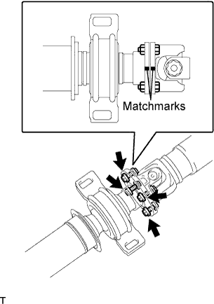
Align the matchmarks on the intermediate shaft flange and the propeller shaft flange, and install the shaft with the 4 bolts, washers and nuts.
- Torque:
- 74 N*m { 755 kgf*cm, 54 ft.*lbf }
-