SFI SYSTEM(w/o EGR System) TERMINALS OF ECM
CHECK ECM
Measure the voltage according to the value(s) in the table below.
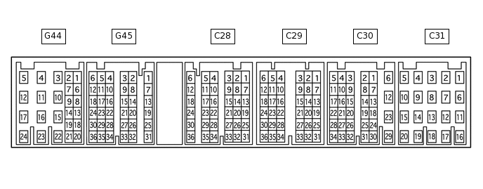
Tip:The standard voltage between each pair of ECM terminals is shown in the table below. The appropriate conditions for checking each pair of terminals are also indicated. The result of checks should be compared with the standard voltage for that pair of terminals, displayed in the "Specified Condition" column. The illustration above can be used as a reference to identify the ECM terminal locations.
Terminal No. (Symbol)
Wiring Color
Terminal Description
Condition
Specified Condition
G44-24 (BATT) - C30-12 (E1)
L - BR
Battery (for measuring battery voltage and for ECM memory)
Always
11 to 14 V
C30-23 (+BM) - C30-12 (E1)
P - BR
Power source of throttle actuator
Always
11 to 14 V
G45-21 (IGSW) - C30-12 (E1)
W - BR
Engine switch
Engine switch on (IG)
11 to 14 V
G44-22 (+B) - C30-12 (E1)
W - BR
Power source of ECM
Engine switch on (IG)
11 to 14 V
G44-23 (+B2) - C30-12 (E1)
W - BR
Power source of ECM
Engine switch on (IG)
11 to 14 V
C29-19 (OC1+) - C29-20 (OC1-)
LG - L-Y
Camshaft timing oil control valve assembly (for Intake Side of Bank 1)
Idling
Pulse generation
(See waveform 1)
C28-19 (OC2+) - C28-20 (OC2-)
L-R - LG
Camshaft timing oil control valve assembly (for Intake Side of Bank 2)
Idling
Pulse generation
(See waveform 1)
C29-21 (OE1+) - C29-22 (OE1-)
B-R - G-W
Camshaft timing oil control valve assembly (for Exhaust Side of Bank 1)
Idling
Pulse generation
(See waveform 1)
C28-21 (OE2+) - C28-22 (OE2-)
B-L- L
Camshaft timing oil control valve assembly (for Exhaust Side of Bank 2)
Idling
Pulse generation
(See waveform 1)
G44-9 (MREL) - C30-12 (E1)
V - BR
EFI relay
Engine switch on (IG)
11 to 14 V
C29-14 (VG) - C29-13 (E2G)
R-W - B-W
Mass air flow meter
Idling, shift lever in P or N, A/C switch off
0.5 to 3.0 V
C29-15 (THA) - C29-7 (E2)
Y - W-R
Intake air temperature sensor
Idling, intake air temperature 20°C (68°F)
0.5 to 3.4 V
C30-17 (THW) - C29-7 (E2)
G - W-R
Engine coolant temperature sensor
Idling, engine coolant temperature 80°C (176°F)
0.2 to 1.0 V
C30-13 (VCTA) - C30-14 (ETA)
R - W
Power source of throttle position sensor (fixed voltage)
Engine switch on (IG)
4.5 to 5.5 V
C30-15 (VTA1) - C30-14 (ETA)
W-R - W
Throttle position sensor (for engine control)
Engine switch on (IG),
throttle valve fully closed
0.5 to 1.1 V
Engine switch on (IG),
throttle valve fully open
3.2 to 4.8 V
C30-16 (VTA2) - C30-14 (ETA)
R-B - W
Throttle position sensor (for sensor malfunction detection)
Engine switch on (IG),
throttle valve fully closed
2.1 to 3.1 V
Engine switch on (IG),
throttle valve fully open
4.6 to 5.0 V
G45-6 (VPA) - G45-3 (EPA)
L - P
Accelerator pedal position sensor (for engine control)
Engine switch on (IG),
accelerator pedal released
0.5 to 1.1 V
Engine switch on (IG),
accelerator pedal fully depressed
2.6 to 4.5 V
G45-5 (VPA2) - G45-1 (EPA2)
GR - W
Accelerator pedal position sensor (for sensor malfunction detection)
Engine switch on (IG),
accelerator pedal released
1.2 to 2.0 V
Engine switch on (IG),
accelerator pedal fully depressed
3.4 to 4.75 V
G45-4 (VCPA) - G45-3 (EPA)
LG - P
Power source of accelerator pedal position sensor (for VPA)
Engine switch on (IG)
4.5 to 5.5 V
G45-2 (VCP2) - G45-1 (EPA2)
R - W
Power source of accelerator pedal position sensor (for VPA2)
Engine switch on (IG)
4.5 to 5.5 V
C31-17 (HA1A) - C31-16 (E04)
B-W - W-B
Air fuel ratio sensor heater
Idling with warm engine
Pulse generation
(See waveform 2)
C31-17 (HA1A) - C31-16 (E04)
B-W - W-B
Air fuel ratio sensor heater
Engine switch on (IG)
11 to 14 V
C31-19 (HA2A) - C31-18 (E05)
R-L - W-B
Air fuel ratio sensor heater
Idling with warm engine
Pulse generation
(See waveform 2)
C31-19 (HA2A) - C31-18 (E05)
R-L - W-B
Air fuel ratio sensor heater
Engine switch on (IG)
11 to 14 V
C30-1 (A1A+) - C30-12 (E1)
Y -BR
Air fuel ratio sensor
Engine switch on (IG)
3.3 V*
C30-2 (A1A-) - C30-12 (E1)
L - BR
Air fuel ratio sensor
Engine switch on (IG)
2.9 V*
C30-7 (A2A+) - C30-12 (E1)
P - BR
Air fuel ratio sensor
Engine switch on (IG)
3.3 V*
C30-8 (A2A-) - C30-12 (E1)
V - BR
Air fuel ratio sensor
Engine switch on (IG)
2.9 V*
C31-12 (HT1B) - C31-11 (E03)
G-Y - W-B
Heated oxygen sensor heater
Idling
Below 3.0 V
C31-12 (HT1B) - C31-11 (E03)
G-Y - W-B
Heated oxygen sensor heater
Engine switch on (IG)
11 to 14 V
C31-13 (HT2B) - C31-11 (E03)
P - W-B
Heated oxygen sensor heater
Idling
Below 3.0 V
C31-13 (HT2B) - C31-11 (E03)
P - W-B
Heated oxygen sensor heater
Engine switch on (IG)
11 to 14 V
C28-2 (OX1B) - C28-1 (EX1B)
B - GR
Heated oxygen sensor
Engine speed maintained at 2500 rpm for 2 minutes after warming up sensor
Pulse generation
(See waveform 3)
C28-4 (OX2B) - C28-3 (EX2B)
W - L-W
C31-6 (#10) - C31-14 (E01)
B - W-B
Fuel injector assembly
Engine switch on (IG)
11 to 14 V
C31-1 (#20) - C31-14 (E01)
L - W-B
Idling
Pulse generation
(See waveform 4)
C31-7 (#30) - C31-14 (E01)
R - W-B
C31-2 (#40) - C31-14 (E01)
G - W-B
C31-8 (#50) - C31-14 (E01)
GR - W-B
C31-3 (#60) - C31-14 (E01)
P-L - W-B
C31-9 (#70) - C31-14 (E01)
V - W-B
C31-4 (#80) - C31-14 (E01)
LG - W-B
C29-11 (KNK1) - C29-12 (EKNK)
W - B
Knock sensor
Engine speed maintained at 4000 rpm after warming up engine
Pulse generation
(See waveform 5)
C29-5 (KNK2) - C29-6 (EKN2)
W - B
C29-9 (KNK3) - C29-10 (EKN3)
G - R
C29-3 (KNK4) - C29-4 (EKN4)
G - R
C28-7 (VV1+) - C28-8 (VV1-)
L-B - B-W
VVT sensor (for Intake Side of Bank 1)
Idling
Pulse generation
(See waveform 6)
C28-12 (VV2+) - C28-11 (VV2-)
G-B - Y
VVT sensor (for Intake Side of Bank 2)
Idling
Pulse generation
(See waveform 6)
C28-13 (EV1+) - C28-14 (EV1-)
W - Y
VVT sensor (for Exhaust Side of Bank 1)
Idling
Pulse generation
(See waveform 17)
C28-18 (EV2+) - C28-17 (EV2-)
V - B-R
VVT sensor (for Exhaust Side of Bank 2)
Idling
Pulse generation
(See waveform 17)
C28-6 (NE+) - C28-5 (NE-)
L - B
Crankshaft position sensor
Idling
Pulse generation
(See waveform 6)
C30-24 (IGT1) - C30-12 (E1)
B-L - BR
Ignition coil assembly (ignition signal)
Idling
Pulse generation
(See waveform 7)
C29-27 (IGT2) - C30-12 (E1)
P-L - BR
C30-27 (IGT3) - C30-12 (E1)
G-W - BR
C29-26 (IGT4) - C30-12 (E1)
P - BR
C29-25 (IGT5) - C30-12 (E1)
W-L - BR
C30-28 (IGT6) - C30-12 (E1)
L-B - BR
C30-26 (IGT7) - C30-12 (E1)
V - BR
C30-25 (IGT8) - C30-12 (E1)
LG - BR
C30-6 (IGF1) - C30-12 (E1)
G-R - BR
Ignition coil assembly (ignition confirmation signal)
Engine switch on (IG)
4.5 to 5.5 V
Idling
Pulse generation
(See waveform 7)
C31-5 (IGF2) - C30-12 (E1)
B-W - BR
Ignition coil assembly (ignition confirmation signal)
Engine switch on (IG)
4.5 to 5.5 V
Idling
Pulse generation
(See waveform 7)
C30-18 (PRG) - C30-12 (E1)
G-B - BR
Purge VSV
Engine switch on (IG)
11 to 14 V
Idling
Pulse generation
(See waveform 8)
G44-18 (SPD) - C30-12 (E1)
R - BR
Speed signal from combination meter
Driving at 20 km/h (12 mph)
Pulse generation
(See waveform 9)
G45-10 (STA) - C30-12 (E1)
W - BR
Starter signal
Cranking
5.5 V or higher
C29-2 (NSW) - C30-12 (E1)
B - BR
Park/Neutral position switch
Engine switch on (IG), shift lever position not in P or N
11 to 14 V
Engine switch on (IG), shift lever in P or N
Below 3.0 V
G45-18 (STP) - C30-12 (E1)
V - BR
Stop light switch
Brake pedal depressed
7.5 to 14 V
Brake pedal released
Below 1.5 V
G44-8 (ST1-) - C30-12 (E1)
B - BR
Stop light switch
(opposite to voltage at STP terminal)
Engine switch on (IG),
brake pedal depressed
Below 1.5 V
Engine switch on (IG),
brake pedal released
7.5 to 14 V
C31-20 (M+) - C31-10 (ME01)
W - W-B
Throttle actuator
Idling with warm engine
Pulse generation
(See waveform 10)
C30-29 (M-) - C31-10 (ME01)
B - W-B
Throttle actuator
Idling with warm engine
Pulse generation
(See waveform 11)
G45-8 (FC) - C30-12 (E1)
G - BR
Fuel pump control
Engine switch on (IG)
11 to 14 V
G44-3 (FPC) - C30-12 (E1)
G - BR
Fuel pump control
Engine switch on (IG)
Below 1.5 V
G44-13 (W) - C30-12 (E1)
V - BR
MIL
Engine switch on (IG)
Below 3.0 V
Idling
11 to 14 V
G45-28 (TC) - C30-12 (E1)
V - BR
Terminal TC of DLC3
Engine switch on (IG)
11 to 14 V
G45-29 (TACH) - C30-12 (E1)
P - BR
Engine speed
Idling
Pulse generation
(See waveform 12)
C28-15 (VCV1) - C29-7 (E2)
P-L - W-R
Power source for sensor (fixed voltage)
Engine switch on (IG)
4.5 to 5.5 V
C28-16 (VCV2) - C29-7 (E2)
G - W-R
Power source for sensor (fixed voltage)
Engine switch on (IG)
4.5 to 5.5 V
C29-28 (ALT) - C30-12 (E1)
L - BR
Generator
Engine switch on (IG)
11 to 14 V
G45-32 (CANH) - C30-12 (E1)
R - BR
CAN communication line
Engine switch on (IG)
Pulse generation
(See waveform 13)
G45-31 (CANL) - C30-12 (E1)
W - BR
CAN communication line
Engine switch on (IG)
Pulse generation
(See waveform 14)
G45-34 (CANP) - C30-12 (E1)
BR - BR
CAN communication line
Engine switch on (IG)
Pulse generation
(See waveform 13)
G45-33 (CANN) - C30-12 (E1)
GR - BR
CAN communication line
Engine switch on (IG)
Pulse generation
(See waveform 14)
C30-19 (ACIS) - C30-12 (E1)
B-W - BR
Vacuum switching valve for ACIS (Acoustic Control Induction System) operation signal
Engine switch on (IG)
11 to 14 V
C28-26 (AIRV) - C30-12 (E1)
P - BR
Air switching valve for secondary air injection system
Engine switch on (IG)
11 to 14 V
C29-23 (AIRP) - C30-12 (E1)
V-W - BR
Air pump control
Engine switch on (IG)
11 to 14 V
C30-20 (AIR1) - C30-12 (E1)
L - BR
Air switching valve for secondary air injection system
Engine switch on (IG)
11 to 14 V
C29-30 (AIDI) - C30-12 (E1)
G - BR
Diagnostic information signal for secondary air injection system
Secondary air injection system operating
Pulse generation
(See waveform 16)
G44-1 (AIP) - C29-7 (E2)
V - W-R
Secondary air injection system pressure signal
Engine switch on (IG)
3.0 to 3.6 V
G44-2 (AIP2) - C29-7 (E2)
B - W-R
Secondary air injection system pressure signal
Engine switch on (IG)
3.0 to 3.6 V
C28-9 (G2) - C28-10 (G2-)
V - Y
Camshaft position sensor
Idling
Pulse generation
(See waveform 15)
G45-26 (DI) - C30-12 (E1)
GR - BR
Fuel pump control
Engine switch on (IG)
0 to 3.0 V
C29-16 (PSP) - C30-12 (E1)
LG-B - BR
Power steering oil pressure switch
Engine switch on (IG)
0.5 to 4.5 V
Tip:*: The ECM terminal voltage is constant regardless of the output voltage from the sensor.
-
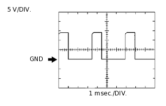
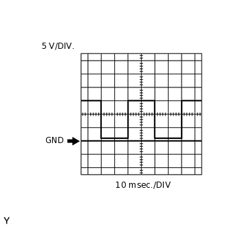
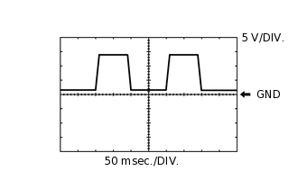
Waveform 1:
Table 1. Camshaft Timing Oil Control Valve Terminal No. (Symbol)
Tool Setting
Condition
C29-19 (OC1+) - C29-20 (OC1-)
5 V/DIV., 1 msec./DIV.
Idling
C28-19 (OC2+) - C28-20 (OC2-)
5 V/DIV., 1 msec./DIV.
Idling
C29-21 (OE1+) - C29-22 (OE1-)
5 V/DIV., 1 msec./DIV.
Idling
C28-21 (OE2+) - C28-22 (OE2-)
5 V/DIV., 1 msec./DIV.
Idling
-
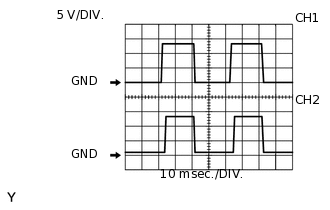
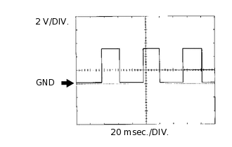
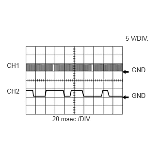
Waveform 2:
Table 2. Air Fuel Ratio Sensor Heater Terminal No. (Symbol)
Tool Setting
Condition
CH1: C31-17 (HA1A) - C31-16 (E04)
5 V/DIV., 10 msec./DIV.
Idling with warm engine
CH2: C31-19 (HA2A) - C31-18 (E05)
5 V/DIV., 10 msec./DIV.
Idling with warm engine
Tip:The wavelength varies in accordance with the engine operating conditions.
-
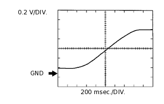
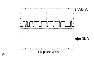
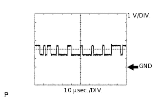
Waveform 3:
Table 3. Heated Oxygen Sensor Terminal No. (Symbol)
Tool Setting
Condition
C28-2 (OX1B) - C28-1 (EX1B)
0.2 V/DIV., 200 msec./DIV.
Engine speed maintained at 2500 rpm for 2 minutes after warming up sensor
C28-4 (OX2B) - C28-3 (EX2B)
0.2 V/DIV., 200 msec./DIV.
Engine speed maintained at 2500 rpm for 2 minutes after warming up sensor
Tip:In the Data List, item O2S B1S2 and O2S B2S2 show the ECM input values from the heated oxygen sensor.
-
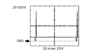
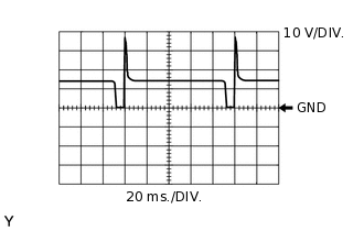
Waveform 4:
Table 4. Fuel Injector Assembly No. 1 (to No. 8) Injection Signal Terminal No. (Symbol)
Tool Setting
Condition
C31-6 (#10) - C31-14 (E01)
20 V/DIV., 20 msec./DIV.
Idling
C31-1 (#20) - C31-14 (E01)
20 V/DIV., 20 msec./DIV.
Idling
C31-7 (#30) - C31-14 (E01)
20 V/DIV., 20 msec./DIV.
Idling
C31-2 (#40) - C31-14 (E01)
20 V/DIV., 20 msec./DIV.
Idling
C31-8 (#50) - C31-14 (E01)
20 V/DIV., 20 msec./DIV.
Idling
C31-3 (#60) - C31-14 (E01)
20 V/DIV., 20 msec./DIV.
Idling
C31-9 (#70) - C31-14 (E01)
20 V/DIV., 20 msec./DIV.
Idling
C31-4 (#80) - C31-14 (E01)
20 V/DIV., 20 msec./DIV.
Idling
Tip:The wavelength becomes shorter as the engine speed increases.
-
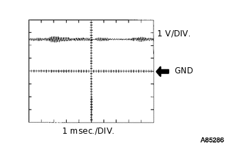
Waveform 5:
Table 5. Knock Sensor Terminal No. (Symbol)
Tool Setting
Condition
C29-11 (KNK1) - C29-12 (EKNK)
1 V/DIV., 1 msec./DIV.
Engine speed maintained at 4000 rpm after warming up engine
C29-5 (KNK2) - C29-6 (EKN2)
1 V/DIV., 1 msec./DIV.
Engine speed maintained at 4000 rpm after warming up engine
C29-9 (KNK3) - C29-10 (EKN3)
1 V/DIV., 1 msec./DIV.
Engine speed maintained at 4000 rpm after warming up engine
C29-3 (KNK4) - C29-4 (EKN4)
1 V/DIV., 1 msec./DIV.
Engine speed maintained at 4000 rpm after warming up engine
Tip:The wavelength becomes shorter as the engine speed increases.
The waveforms and amplitudes displayed differ slightly depending on the vehicle.
-
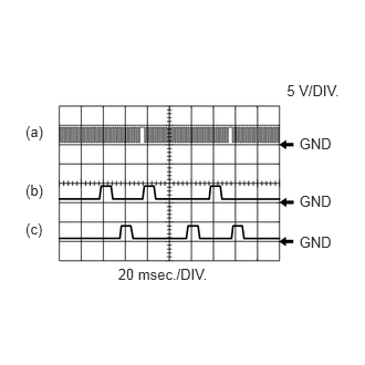
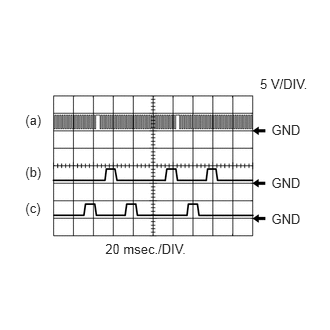
Waveform 6:
Table 6. Crankshaft Position Sensor and VVT Sensor for Intake Side Terminal No. (Symbol)
Tool Setting
Condition
(a) C28-6 (NE+) - C28-5 (NE-)
5 V/DIV., 20 msec./DIV.
Idling after engine warmed up
(b) C28-7 (VV1+) - C28-8 (VV1-)
5 V/DIV., 20 msec./DIV.
Idling after engine warmed up
(c) C28-12 (VV2+) - C28-11 (VV2-)
5 V/DIV., 20 msec./DIV.
Idling after engine warmed up
Tip:The wavelength becomes shorter as the engine speed increases.
-
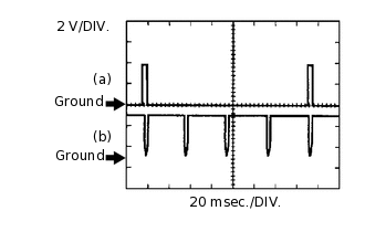
Waveform 7:
Table 7. Ignition Coil Assembly Signal (IGT and IGF Signal) Terminal No. (Symbol)
Tool Setting
Condition
(a) C30-24 (IGT1) - C30-12 (E1)
2 V/DIV., 20 msec./DIV.
Idling
(a) C29-27 (IGT2) - C30-12 (E1)
2 V/DIV., 20 msec./DIV.
Idling
(a) C30-27 (IGT3) - C30-12 (E1)
2 V/DIV., 20 msec./DIV.
Idling
(a) C29-26 (IGT4) - C30-12 (E1)
2 V/DIV., 20 msec./DIV.
Idling
(a) C29-25 (IGT5) - C30-12 (E1)
2 V/DIV., 20 msec./DIV.
Idling
(a) C30-28 (IGT6) - C30-12 (E1)
2 V/DIV., 20 msec./DIV.
Idling
(a) C30-26 (IGT7) - C30-12 (E1)
2 V/DIV., 20 msec./DIV.
Idling
(a) C30-25 (IGT8) - C30-12 (E1)
2 V/DIV., 20 msec./DIV.
Idling
(b) C30-6 (IGF1) - C30-12 (E1)
2 V/DIV., 20 msec./DIV.
Idling
(b) C31-5 (IGF2) - C30-12 (E1)
2 V/DIV., 20 msec./DIV.
Idling
Tip:The wavelength becomes shorter as the engine speed increases.
-
Waveform 8:
Table 8. Purge VSV Terminal No. (Symbol)
Tool Setting
Condition
C30-18 (PRG) - C30-12 (E1)
10 V/DIV., 20 msec./DIV.
Idling
Tip:If the waveform is not similar to the illustration, check the waveform again after idling for 10 minutes or more.
-
Waveform 9:
Table 9. Vehicle Speed Signal Terminal No. (Symbol)
Tool Setting
Condition
G44-18 (SPD) - C30-12 (E1)
2 V/DIV., 20 msec./DIV.
Driving at 20 km/h (12 mph)
Tip:The wavelength becomes shorter as the vehicle speed increases.
-
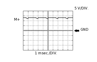
Waveform 10:
Table 10. Throttle Actuator Positive Terminal Signal Terminal No. (Symbol)
Tool Setting
Condition
C31-20 (M+) - C31-10 (ME01)
5 V/DIV., 1 msec./DIV.
Idling with warm engine
Tip:The duty ratio varies depending on the throttle actuator operation.
-
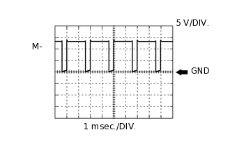
Waveform 11:
Table 11. Throttle Actuator Negative Terminal Signal Terminal No. (Symbol)
Tool Setting
Condition
C30-29 (M-) - C31-10 (ME01)
5 V/DIV., 1 msec./DIV.
Idling with warm engine
Tip:The duty ratio varies depending on the throttle actuator operation.
-
Waveform 12:
Table 12. Engine Speed Signal Terminal No. (Symbol)
Tool Setting
Condition
G45-29 (TACH) - C30-12 (E1)
5 V/DIV., 10 msec./DIV.
Idling
Tip:The wavelength becomes shorter as the engine speed increases.
-
Waveform 13:
Table 13. CAN Communication Signal (Reference) Terminal No. (Symbol)
Tool Setting
Condition
G45-32 (CANH) - C30-12 (E1)
1 V/DIV., 10 μsec./DIV.
Engine stopped and engine switch on (IG)
G45-34 (CANP) - C30-12 (E1)
1 V/DIV., 10 μsec./DIV.
Engine stopped and engine switch on (IG)
Tip:The waveform varies depending on the CAN communication signal.
-
Waveform 14:
Table 14. CAN Communication Signal (Reference) Terminal No. (Symbol)
Tool Setting
Condition
G45-31 (CANL) - C30-12 (E1)
1 V/DIV., 10 μsec./DIV.
Engine stopped and engine switch on (IG)
G45-33 (CANN) - C30-12 (E1)
1 V/DIV., 10 μsec./DIV.
Engine stopped and engine switch on (IG)
Tip:The waveform varies depending on the CAN communication signal.
-
Waveform 15:
Table 15. Crankshaft Position Sensor and Camshaft Position Sensor Terminal No. (Symbol)
Tool Setting
Condition
CH1: C28-6 (NE+) - C28-5 (NE-)
5 V/DIV., 20 msec./DIV.
Idling after engine warmed up
CH2: C28-9 (G2) - C28-10 (G2-)
5 V/DIV., 20 msec./DIV.
Idling after engine warmed up
Tip:The wavelength becomes shorter as the engine speed increases.
-
Waveform 16:
Table 16. Terminal DI of Air Injection Control Driver Terminal No. (Symbol)
Tool Setting
Condition
C29-30 (AIDI) - C30-12 (E1)
5 V/DIV., 50 msec./DIV.
Performing system check using tester (Secondary Air Injection Check)
Tip:The wavelength changes when the air injection control driver detects malfunctions in the air injection system (Click here).
-
Waveform 17:
Table 17. Crankshaft Position Sensor and VVT Sensor for Exhaust Side Terminal No. (Symbol)
Tool Setting
Condition
(a) C28-6 (NE+) - C28-5 (NE-)
5 V/DIV., 20 msec./DIV.
Idling after engine warmed up
(b) C28-13 (EV1+) - C28-14 (EV1-)
5 V/DIV., 20 msec./DIV.
Idling after engine warmed up
(c) C28-18 (EV2+) - C28-17 (EV2-)
5 V/DIV., 20 msec./DIV.
Idling after engine warmed up
Tip:The wavelength becomes shorter as the engine speed increases.