CVT SYSTEM
-
CONSTRUCTION
-
The widths of the grooves of the pulleys are changed through hydraulic control.
-
During acceleration, the action of shift solenoid valve DS1 increases the fluid inflow volume to the primary pulley, thus narrowing the width of the pulley groove.
-
During deceleration, the action of shift solenoid valve DS2 increases the outflow volume to the primary pulley, thus widening the width of the pulley groove.
-
The secondary pulley is hydraulically controlled by shift solenoid valve SLS. Shift solenoid valve SLS controls the belt clamping pressure to ensure proper power transmission efficiency.
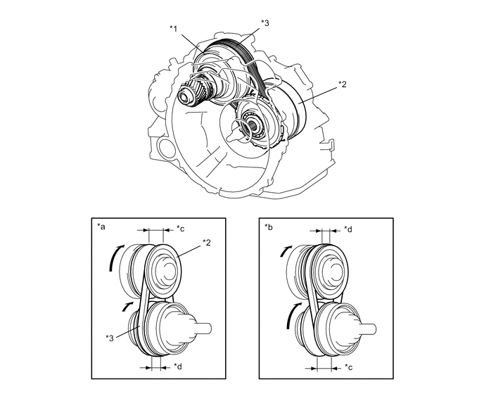
*1 Secondary Pulley *2 Primary Pulley *3 Steel Belt - - *a Pulley Ratio (Low) *b Pulley Ratio (High) *c Groove Width (Large) *d Groove Width (Small) -
The primary pulley uses a double piston construction. 2 chambers generate hydraulic pressure to vary the groove width. This has resulted in a compact and lightweight assembly.
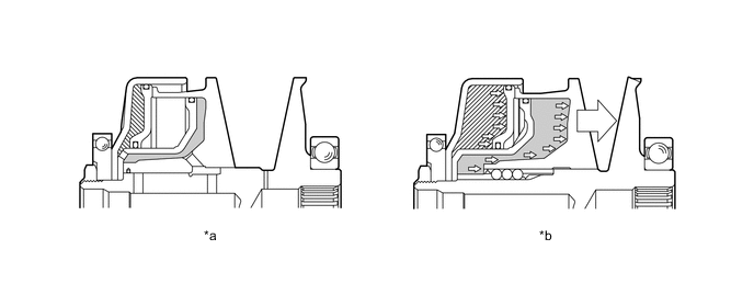
*a Pulley Ratio (Low) *b Pulley Ratio (High) 
Chamber A 
Chamber B -
The steel belt consists of elements and 2 rows of steel rings. In contrast to the chains and V-belts that transmit power through the use of tensile force, the steel belt uses the compressive action (pushing force) of the elements to transmit power.
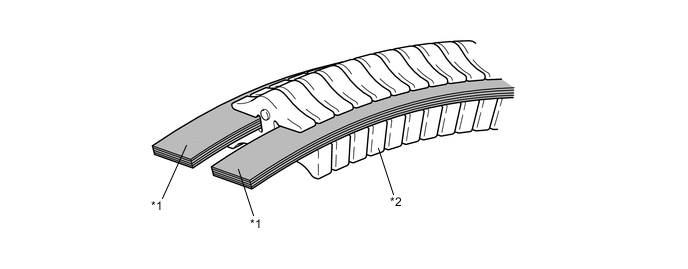
*1 Steel Ring *2 Element
-
-
OPERATION
-
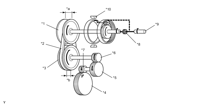
The changing of the pulley ratio is accomplished in a continuously variable manner by varying the widths of the grooves of the primary and secondary pulleys.
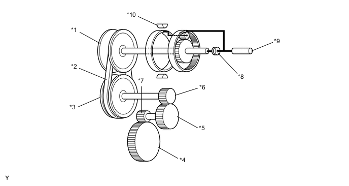
*1 Primary Pulley *2 Steel Belt *3 Secondary Pulley *4 Differential Ring Gear *5 Reduction Driven Gear *6 Reduction Drive Gear *7 Differential Drive Pinion *8 Forward Clutch *9 Input Shaft *10 Reverse Brake Figure 1. Pulley Ratio Low (Shift Lever in D)
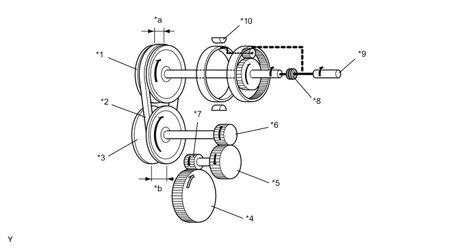
*1 Primary Pulley *2 Steel Belt *3 Secondary Pulley *4 Differential Ring Gear *5 Reduction Driven Gear *6 Reduction Drive Gear *7 Differential Drive Pinion *8 Forward Clutch (On) *9 Input Shaft *10 Reverse Brake (Off) *a Groove Width (Large) *b Groove Width (Small) Figure 2. Pulley Ratio High (Shift Lever in D)
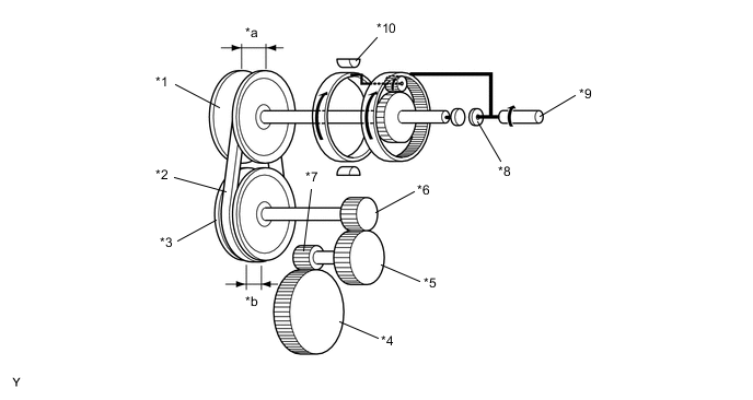
*1 Primary Pulley *2 Steel Belt *3 Secondary Pulley *4 Differential Ring Gear *5 Reduction Driven Gear *6 Reduction Drive Gear *7 Differential Drive Pinion *8 Forward Clutch (On) *9 Input Shaft *10 Reverse Brake (Off) *a Groove Width (Small) *b Groove Width (Large) Figure 3. Neutral (Shift Lever in N)
*1 Primary Pulley *2 Steel Belt *3 Secondary Pulley *4 Differential Ring Gear *5 Reduction Driven Gear *6 Reduction Drive Gear *7 Differential Drive Pinion *8 Forward Clutch (Off) *9 Input Shaft *10 Reverse Brake (Off) *a Groove Width (Large) *b Groove Width (Small) Figure 4. Reverse (Shift Lever in R)
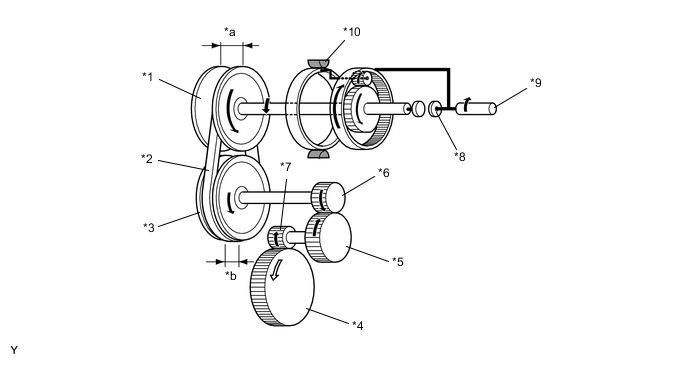
*1 Primary Pulley *2 Steel Belt *3 Secondary Pulley *4 Differential Ring Gear *5 Reduction Driven Gear *6 Reduction Drive Gear *7 Differential Drive Pinion *8 Forward Clutch (Off) *9 Input Shaft *10 Reverse Brake (On) *a Groove Width (Large) *b Groove Width (Small)
-