РАСПРЕДВАЛ УСТАНОВКА
-
INSTALL CAMSHAFT TIMING GEAR
-
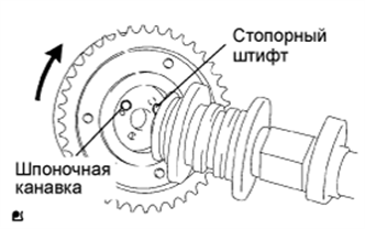
Put the camshaft timing gear and camshaft together by aligning the key groove and straight pin.
-
Check that there is no gap between the gear's flange and the camshaft.
-
With the camshaft timing gear fixed in place, tighten the flange bolt.
- Torque:
- 78 N*m { 795 kgf*cm, 58 ft.*lbf }
-
-
INSTALL VALVE STEM CAP
-
Apply clean engine oil to the valve stem tip, and install the valve stem cap.
Note
Install the cap to the same place it was removed from.
-
-
INSTALL VALVE LASH ADJUSTER
Note
-
Keep the lash adjuster free from dirt and foreign objects.
-
Only use clean engine oil.
-
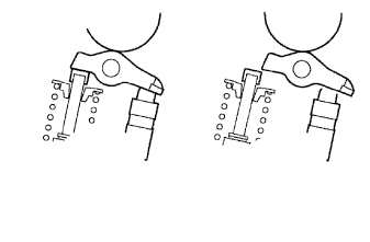
Place the lash adjuster into a container full of engine oil.
-
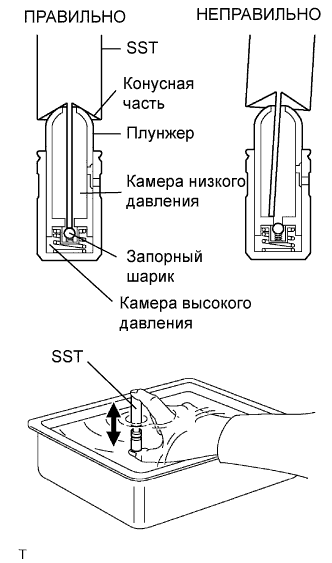
Insert SST's tip into the lash adjuster's plunger and use the tip to press down on the checkball inside the plunger.
- SST
- 09276-75010
-
Squeeze the SST and lash adjuster together to move the plunger up and down 5 to 6 times.
-
Check the movement of the plunger and bleed air.
OK Plunger moves up and down. Note
When bleeding high-pressure air from the compression chamber, make sure that the tip of the SST is actually pressing the checkball as shown in the illustration. If the checkball is not pressed, air will not bleed.
-
After bleeding air, remove SST. Then, try to quickly and firmly press the plunger with a finger.
OK Plunger is very difficult to move. If the result is not as specified, replace the lash adjuster.
-
Install the lash adjuster.
Tech Tips
Repeat the same procedures and install the remaining lash adjusters.
Note
Install the lash adjuster to the same place it was removed from.
-
-
INSTALL VALVE ROCKER ARM
-
Apply clean engine oil to the valve lash adjuster tips and valve stem cap surfaces. Then install the valve rocker arms.
Note
Install the valve stem cap and valve rocker arm to the same place it was removed from.
-
-
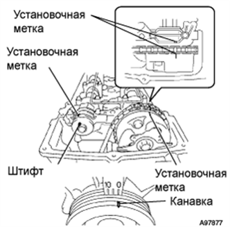
INSTALL CAMSHAFT
-
Apply clean engine oil to the camshaft's cam portion and the cylinder head journals.
-
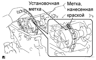
Install the timing chain on the camshaft timing gear, with the painted mark of the link aligned with the timing mark of the camshaft timing gear.
-
Set the 2 camshafts as shown in the illustration.
Note
-
Align the paint mark and timing mark before setting the camshaft.
-
Before and after setting the camshaft and No. 2 camshaft, check that the rocker arm is firmly set to the lash adjuster.
-
-
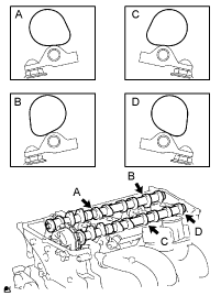
Loosely install the No. 1 camshaft bearing cap.
-
Check the proper location of each camshaft bearing cap and install each one.
-
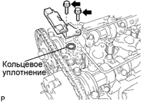
Install a new O-ring to the No. 1 camshaft bearing cap.
-
Temporarily install the oil delivery pipe.
-
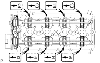
Tighten the 21 bolts and 20 washers in the order shown in the illustration.
- Torque:
- 12 N*m { 122 kgf*cm, 9 ft.*lbf, for bolt A }
- 15.5 N*m { 158 kgf*cm, 11 ft.*lbf, for except bolt A }
-
-
INSTALL CAMSHAFT TIMING SPROCKET
-
Rotate the camshaft so that the camshaft's timing mark and the No. 2 camshaft knock pin are as shown in the illustration.
-
Turn the crankshaft pulley, and align its groove with timing mark 0 of the timing chain cover.
-
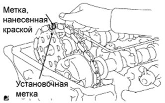
Install the timing chain on the camshaft timing sprocket, with the paint mark aligned with the timing marks on the camshaft timing sprocket.
-
Align the No. 2 camshaft knock pin and camshaft timing sprocket's pin hole. Then install the camshaft timing sprocket to the No. 2 camshaft.
Note
If the knock pin and pin hole are difficult to align, slightly rotate the No. 2 camshaft to the left and right using the camshaft's hexagon-shaped part. Then attempt alignment again.
-
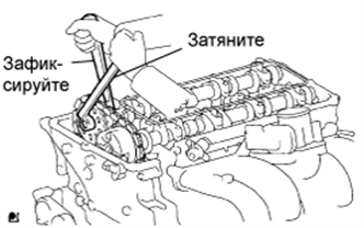
Fix the camshaft with a wrench, and then tighten the sprocket bolt.
- Torque:
- 78 N*m { 795 kgf*cm, 58 ft.*lbf }
-
Remove the hexagon wrench from the chain tensioner.
-
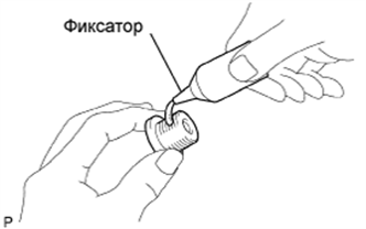
Apply adhesive to 2 or 3 threads of the timing chain cover plug.
Adhesive Toyota Genuine Adhesive 1324, Three Bond 1324 or equivalent Note
Remove any oil from the bolt hole.
-
Using a 10 mm socket hexagon wrench, install the timing gear case plug.
- Torque:
- 16.6 N*m { 169 kgf*cm, 12 ft.*lbf }
-
-
INSTALL TIMING CHAIN GUIDE
-
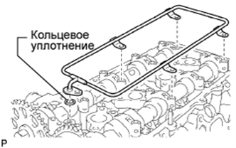
Install a new O-ring to the camshaft bearing cap.
-
Install the timing chain guide with the 2 bolts.
- Torque:
- 10 N*m { 102 kgf*cm, 7 ft.*lbf }
-
-
INSTALL CYLINDER HEAD COVER
-
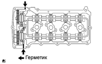
Install the 2 gaskets to the cylinder head cover.
-
Remove any old packing (FIPG) material.
-
Apply seal packing to 2 locations as shown in the illustration.
Seal packing Toyota Genuine Seal Packing Black, Three Bond 1207B or equivalent Note
-
Remove any oil from the contact surface.
-
Install the cylinder head cover within 3 minutes after applying seal packing.
-
Do not apply engine oil for at least 2 hours after installing.
-
-
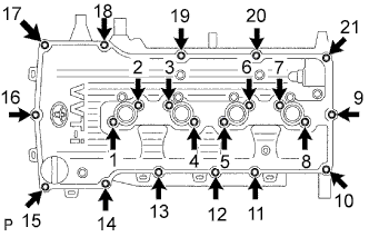
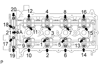
Loosely install the head cover with the 19 bolts and 2 nuts.
-
Uniformly tighten the 19 bolts and 2 nuts in the sequence shown in the illustration.
- Torque:
- 9.0 N*m { 92 kgf*cm, 80 in.*lbf }
-
In numerical order, confirm that the bolts labeled 1 to 18 are tightened to the torque specification. Tighten the bolts as necessary.
-
Connect the wire harness to the 6 clamps.
-
-
INSTALL IGNITION COIL
-
Install the ignition coil with the bolt.
- Torque:
- 9.0 N*m { 92 kgf*cm, 80 in.*lbf }
-
-
INSTALL INTAKE AIR CONNECTOR
-
Install the intake air connector with the 2 bolts, and tighten the 2 hose clamps.
- Torque:
- 8.0 N*m { 82 kgf*cm, 71 in.*lbf, for intake air connector }
- 5.0 N*m { 51 kgf*cm, 44 in.*lbf, for hose clamp }
-
-
INSTALL DRIVE BELT
-
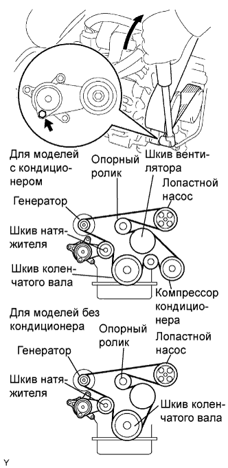
Установите приводной ремень на все шкивы, кроме шкива натяжителя приводного ремня.
-
С помощью шестигранника, указанного на рисунке стрелкой, сдвиньте шкив натяжителя вниз, а затем установите приводной ремень на шкив натяжителя.
Note
-
Приводной ремень должен быть обращен к шкиву натяжителя тыльной стороной.
-
Проверьте правильность посадки приводного ремня на шкив и ролик.
-
-
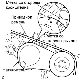
После установки нового ремня убедитесь, что указатель натяжителя находится в диапазоне A, как показано на рисунке.
-
-
CONNECT CABLE TO NEGATIVE BATTERY TERMINAL
-
PERFORM INITIALIZATION
-
Perform initialization Click here.
Note
Certain systems need to be initialized after disconnecting and reconnecting the cable from the negative (-) battery terminal.
-
-
CHECK FOR ENGINE OIL LEAKS
-
Start the engine, and check that there are no oil leaks after performing maintenance.
-
-
CHECK FOR ENGINE COOLANT LEAKS
CAUTION:
Не снимайте пробку радиатора, пока двигатель и радиатор не остынут. Выброс горячей охлаждающей жидкости и пара под давлением может стать причиной серьезных ожогов.
-
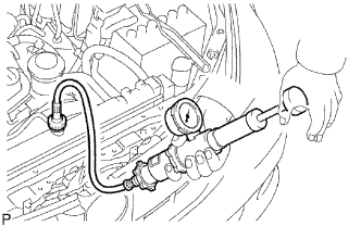
Заполните радиатор охлаждающей жидкостью и подсоедините приспособление для опрессовки системы охлаждения и проверки пробки радиатора.
-
Прогрейте двигатель.
-
С помощью приспособления для опрессовки системы охлаждения и проверки пробки радиатора увеличьте давление в радиаторе до 118 кПа (1,2 кгс/см2, 17,1 фунтов на кв. дюйм) и убедитесь, что давление не падает.
Если давление снижается, проверьте на наличие утечек шланги, радиатор и насос системы охлаждения. При отсутствии внешних утечек проверьте блок цилиндров и головку блока цилиндров.
-
-
INSPECT ENGINE IDLE SPEED AND IGNITION TIMING
-
Warm up and stop the engine.
Note
A warmed up engine should have an engine coolant temperature of over 80°C (176°F), have an engine oil temperature of 60°C (140°F), and the engine rpm should be stabilized.
-
Check the idle speed control system.
-
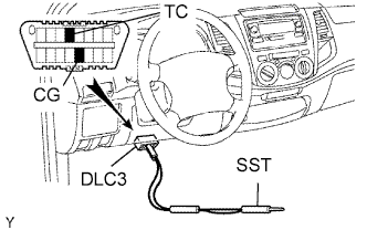
Using SST, connect terminals TC and CG of the DLC3.
- SST
- 09843-18040
-
Start the engine at idle.
Note
-
Confirm the terminal numbers before connecting them. Connection with a wrong terminal can damage the engine.
-
Turn off all electrical systems before connecting the terminals.
-
When checking ISC function, the transmission should be in the neutral position.
-
-
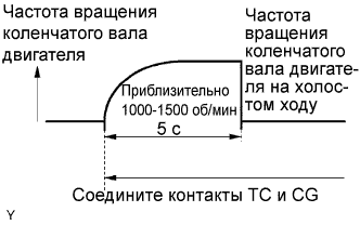
After connecting terminals (TC and CG), check that the engine speed changes to approximately 1,000 to 1,500 rpm for 5 seconds, and then returns to idle speed.
If the result is not as specified, check the throttle body, DTC Click here and wire harness.
-
-
-
CHECK CO/HC
-
Start and warm up the engine.
-
Run the engine at 2,500 rpm for approximately 180 seconds and idle the engine.
-
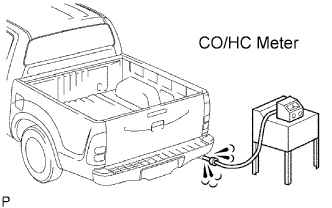
Insert CO/HC meter testing probe at least 40 cm (1.3 ft.) into the tailpipe.
-
Check CO/HC concentration at idle.
Standard idle CO concentration 0 to 0.5 % Standard idle HC concentration Applicable local regulation -
If the CO/HC concentration is not as specified, perform troubleshooting in the order given below.
-
Check the heated oxygen sensor operation Click here.
-
See the table below for possible causes, and then inspect and repair the applicable causes if necessary.
CO HC Problems Causes Normal High Rough idle
-
Faulty ignitions:
-
Incorrect timing
-
Plugs are contaminated, shorted or gaps are defective
-
Incorrect valve clearance
-
Leaks in intake and exhaust valves
-
Leaks in cylinders
Low High Rough idle
(Fluctuating HC reading)
-
Vacuum leaks:
-
PCV hoses
-
Intake manifold
-
Throttle body
-
Brake booster line
-
Lean mixture causing misfire
High High Rough idle
(Black smoke from exhaust)
-
Restricted air filter
-
Plugged PCV valve
-
Faulty SFI system:
-
Faulty pressure regulator
-
Defective ECT sensor
-
Defective Mass Air Flow (MAF) meter
-
Faulty ECM
-
Faulty injectors
-
Faulty throttle position sensor
-
-
-
-
CHECK FUNCTION OF THROTTLE BODY
-
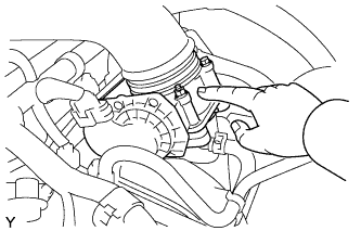
Проверьте, слышен ли звук работающего электродвигателя привода дроссельной заслонки.
-
Включите зажигание.
-
Нажимая педаль акселератора, убедитесь в наличии звука работающего двигателя. Убедитесь, что двигатель не создает шум трения.
Если слышен шум трения, замените корпус дроссельной заслонки.
-
-
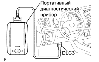
Проверьте датчик положения дроссельной заслонки.
-
Подсоедините портативный диагностический прибор к DLC3.
-
Включите зажигание.
-
Убедитесь, что в режиме Current Data процентное значение угла поворота дроссельной заслонки (Throttle Pos) не выходит за пределы номинального диапазона.
Номинальное значение открывания дроссельной заслонки 60% или более Note
Во время проверки степени открывания дроссельной заслонки рычаг переключения передач должен находиться в нейтральном положении.
Если значение составляет менее 60%, замените корпус дроссельной заслонки.
-
-