STEERING GEAR REMOVAL

CAUTION / NOTICE / HINT
Tech Tips
-
Use the same procedure for RHD and LHD vehicles.
-
The procedure listed below is for LHD vehicles.
PROCEDURE
-
PLACE FRONT WHEELS FACING STRAIGHT AHEAD
-
SECURE STEERING WHEEL ASSEMBLY
-
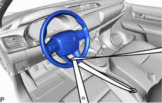
Secure the steering wheel assembly with the seat belt in order to prevent rotation.
Tech Tips
This operation is useful to prevent damage to the spiral cable sub-assembly.
-
-
REMOVE FRONT WHEELS
-
REMOVE NO. 1 ENGINE UNDER COVER ASSEMBLY (for 2WD (w/ No. 1 Engine Under Cover Assembly))
-
REMOVE NO. 1 ENGINE UNDER COVER ASSEMBLY (for 4WD and Pre-Runner)
-
REMOVE NO. 1 ENGINE UNDER COVER (for 2WD (w/ No. 1 Engine Under Cover))
-
REMOVE NO. 2 ENGINE UNDER COVER (for 4WD and Pre-Runner)
-
REMOVE ENGINE UNDER BRACE SUB-ASSEMBLY (for 2WD)
-
w/o No. 1 Engine Under Cover Assembly:
-
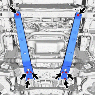
Remove the 8 bolts and 2 engine under brace sub-assemblies.
-
-
w/ No. 1 Engine Under Cover Assembly:
-
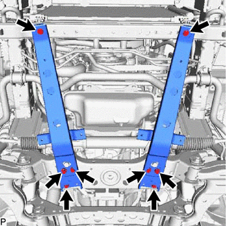
Remove the 8 bolts and 2 engine under brace sub-assemblies.
-
-
-
REMOVE NO. 1 RACK BOOT PROTECTOR SUB-ASSEMBLY (for 2WD (w/ No. 1 Rack Boot Protector Sub-Assembly))
-
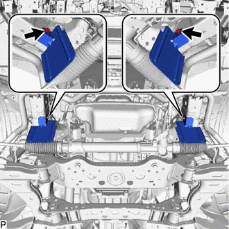
Remove the 2 bolts and 2 rack boot protector sub-assemblies.
-
-
DISCONNECT TIE ROD END SUB-ASSEMBLY LH
-
Remove the cotter pin and nut.
-
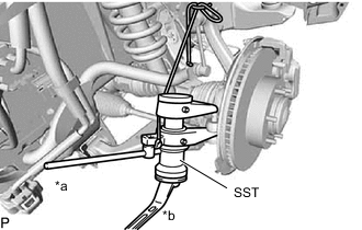
*a Hold *b Turn Using SST, disconnect the tie rod end sub-assembly LH from the front axle hub assembly LH.
- SST
- 09628-00011
-
-
DISCONNECT TIE ROD END SUB-ASSEMBLY RH
Tech Tips
Use the same procedure described for the LH side.
-
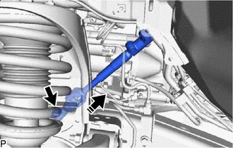
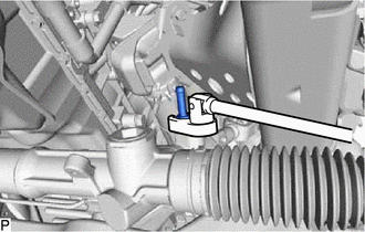
DISCONNECT STEERING SLIDING YOKE
-
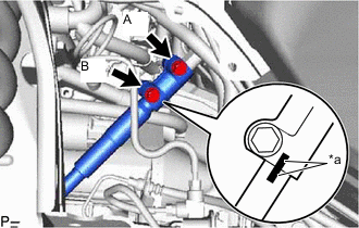
*a Matchmark Place matchmarks on the steering sliding yoke and No. 2 steering intermediate shaft sub-assembly.
-
Loosen the bolt labeled A.
-
Remove the bolt labeled B.
-

Install in this Direction Disconnect the steering sliding yoke from the No. 2 steering intermediate shaft sub-assembly.
-
-
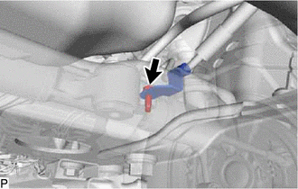
REMOVE NO. 2 STEERING INTERMEDIATE SHAFT SUB-ASSEMBLY
-
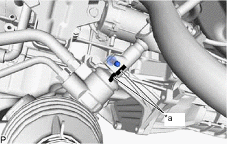
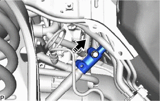
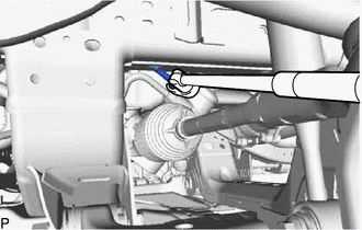
*a Matchmark Place matchmarks on the No. 2 steering intermediate shaft sub-assembly and power steering link assembly.
-
Install in this Direction Remove the bolt and No. 2 steering intermediate shaft sub-assembly from the power steering link assembly.
Note
If the No. 2 steering intermediate shaft sub-assembly is struck, replace it with a new one.
-
-
REMOVE FRONT DIFFERENTIAL CARRIER ASSEMBLY (for 4WD)
-
REMOVE POWER STEERING LINK ASSEMBLY (for 2WD)
-
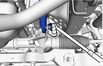
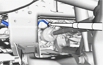
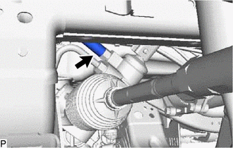
Using a union nut wrench, loosen the flare nut and disconnect the pressure feed tube assembly.
-
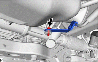
Remove the bolt and disconnect the pressure feed tube assembly bracket from the power steering link assembly.
-
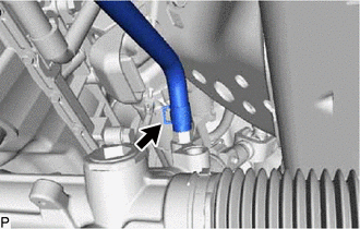
Slide the clip and disconnect the return hose.
-
Using a union nut wrench, disconnect the steering gear outlet return tube.
-
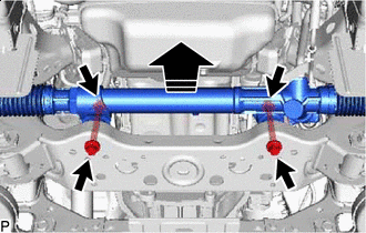
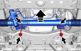
Remove in this Direction Fix the 2 nuts in place and remove the 2 bolts and 2 washers. Then remove the power steering link assembly from the front suspension member.
Note
Never turn the nut. Be sure to turn the bolt.
-
-
REMOVE POWER STEERING LINK ASSEMBLY (for 4WD and Pre-Runner)
-
Using a union nut wrench, loosen the flare nut and disconnect the pressure feed tube assembly.
-
Remove the bolt and disconnect the pressure feed tube assembly bracket from the power steering link assembly.
-
Slide the clip and disconnect the return hose.
-
Using a union nut wrench, disconnect the steering gear outlet return tube.
-
Remove in this Direction Fix the 2 nuts in place and remove the 2 bolts and 2 washers. Then remove the power steering link assembly from the front suspension member.
Note
Never turn the nut. Be sure to turn the bolt.
-