ТОПЛИВНАЯ СИСТЕМА ДВИГАТЕЛЯ COMMON RAIL СНЯТИЕ

Note
-
When replacing the parts in the following chart (A), replace the No. 1 injection pipe sub-assembly, No. 2 injection pipe sub-assembly and/or fuel inlet pipe sub-assembly with new ones.
Replaced Parts (A) Pipes Requiring New Replacement
-
Injector assembly (including shuffling the injector assemblies between the cylinders)
-
Common rail assembly
-
Cylinder head sub-assembly
-
No. 1 injection pipe sub-assembly
-
No. 2 injection pipe sub-assembly
Supply pump assembly Supply pump assembly
-
Common rail assembly
-
Cylinder block sub-assembly
-
Cylinder head sub-assembly
-
Cylinder head gasket
-
Timing chain case assembly
-
No. 1 injection pipe sub-assembly
-
No. 2 injection pipe sub-assembly
-
Fuel inlet pipe sub-assembly
-
-
After removing the No. 1 injection pipe sub-assembly, No. 2 injection pipe sub-assembly and/or fuel inlet pipe sub-assembly, clean them with a brush and compressed air.
-
The injector assembly is a precision instrument. Do not use the injector assembly if it is struck or dropped.
-
Make sure foreign matter does not enter the fuel path.
-
PRECAUTION
Note
After turning the ignition switch off, waiting time may be required before disconnecting the cable from the battery terminal. Therefore, make sure to read the disconnecting the cable from the battery terminal notice before proceeding with work Click here.
-
DISCONNECT CABLE FROM NEGATIVE BATTERY TERMINAL
Note
When disconnecting the cable, some systems need to be initialized after the cable is reconnected Click here.
-
REMOVE EGR COOLER ASSEMBLY
-
REMOVE WIRING HARNESS CLAMP BRACKET
-
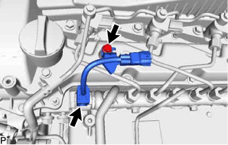
Disconnect the pressure discharge valve connector from the common rail assembly.
-
Remove the bolt and wiring harness clamp bracket from the cylinder head cover sub-assembly.
-
-
REMOVE NO. 1 AND NO. 2 INJECTION PIPE SUB-ASSEMBLY
Note
After removing the No. 1 and No. 2 injection pipe sub-assemblies, cover the common rail assembly with electrical tape to prevent dirt or foreign objects from entering the pipe inlet. Also, protect the injector inlets with electrical tape or plastic bags.
-
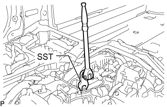
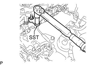
Using SST, loosen the No. 1 and No. 2 injection pipe sub-assemblies and 8 union nuts of the fuel injector assembly side and common rail assembly side.
- SST
- 09245-11010
-
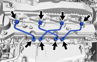
Remove the 2 No. 1 injection pipe sub-assemblies and 2 No. 2 injection pipe sub-assemblies.
Note
When removing the No. 1 injection pipe sub-assembly and No. 2 injection pipe sub-assembly, store the injector assemblies in the correct order so that they can be returned to their original locations when reassembling.
-
-
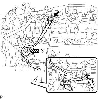
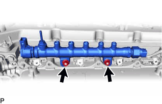
REMOVE FUEL INLET PIPE SUB-ASSEMBLY
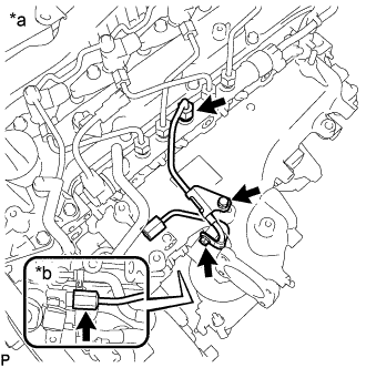
Text in Illustration *a Common Rail Assembly Side *b Fuel Supply Pump Assembly Side
-
Remove the 2 bolts, No. 1 injection pipe clamp and No. 2 injection pipe clamp.
-
Using SST, loosen the fuel inlet pipe sub-assembly union nut of the common rail assembly side.
- SST
- 09245-11010
Note
If the No. 1 or No. 2 injection pipe clamp is removed from the inlet pipe sub-assembly, replace the No. 1 or No. 2 injection clamp with a new one.
-
Using a 19 mm union nut wrench, loosen the inlet pipe sub-assembly union nut of the fuel supply pump assembly side.
-
-
REMOVE NO. 4 FUEL PIPE SUB-ASSEMBLY
-
Disconnect the No. 4 fuel pipe sub-assembly from the No. 1 fuel pipe Click here.
Text in Illustration 
Union Bolt 
Bolt -
Remove the bolt from the intake manifold.
-
Remove the 2 union bolts and 2 gaskets from the supply pump assembly and fuel filter.
-
-
REMOVE NO. 4 FUEL HOSE
-
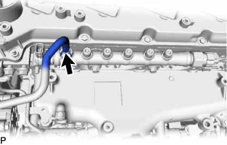
Slide the clamp and disconnect the No. 4 fuel hose from the common rail assembly.
-
-
REMOVE COMMON RAIL ASSEMBLY
-
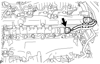
Detach the wire harness clamp.
-
Disconnect the fuel pressure sensor connector from the common rail assembly.
-
Remove the 2 nuts and common rail assembly.
Note
Do not remove the pressure discharge valve or fuel pressure sensor.
-