ВЫХОДНОЙ ВАЛ УСТАНОВКА
-
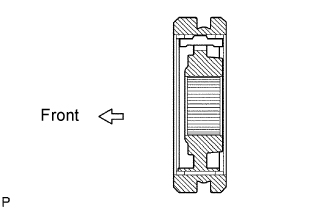
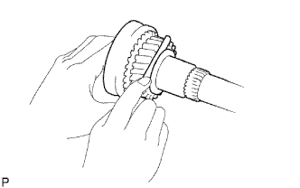
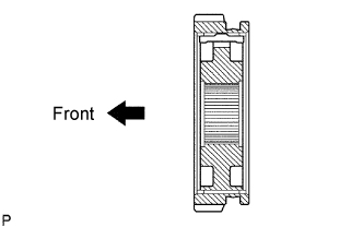
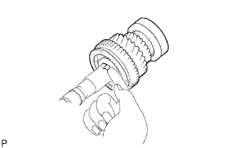
INSTALL NO. 2 TRANSMISSION CLUTCH HUB
-
Coat the hub sleeve with gear oil, and install it to the clutch hub.
Note
Be sure to set the hub sleeve to the clutch hub in the correct direction.
-
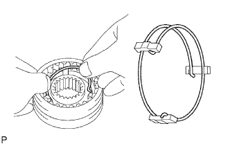
Install the 3 synchromesh shifting keys to the clutch hub with the 2 synchromesh shifting key springs.
Tech Tips
Do not set both openings of the shifting key springs in the same position.
-
-
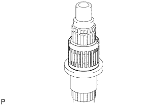
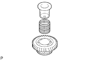
INSTALL 3RD GEAR NEEDLE ROLLER BEARING
-
Coat the needle roller bearing with gear oil, and install it to the output shaft.
-
-
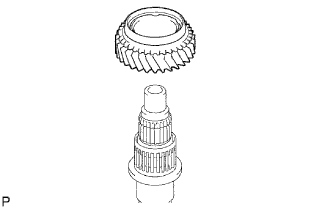
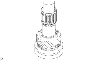
INSTALL 3RD GEAR
-
Coat the 3rd gear with gear oil, and install it to the output shaft.
-
-
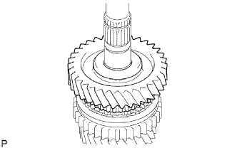
INSTALL NO. 2 SYNCHRONIZER RING
-
Coat the synchronizer ring with gear oil, and install it to the 3rd gear.
-
-
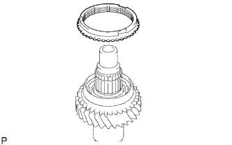
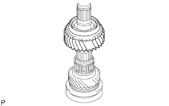
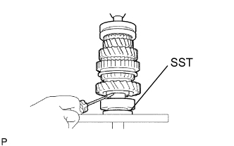
INSTALL NO. 2 TRANSMISSION CLUTCH HUB
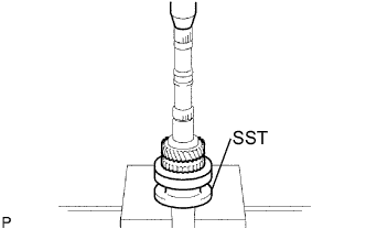
-
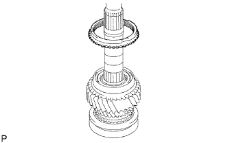
Using SST and a press, press in the No. 2 clutch hub to the output shaft.
- SST
- 09316-60011 ( 09316-00021 )
-
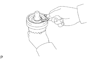
Select a clutch hub shaft snap ring that will allow minimal axial play.
Standard clearance 0.10 mm (0.039 in.) or less Standard clutch hub shaft snap ring thickness Mark Thickness C-1 1.75 to 1.80 mm (0.0689 to 0.0709 in.) D 1.80 to 1.85 mm (0.0709 to 0.0728 in.) D-1 1.85 to 1.90 mm (0.0728 to 0.0748 in.) E 1.90 to 1.95 mm (0.0748 to 0.0768 in.) E-1 1.95 to 2.00 mm (0.0768 to 0.0787 in.) F 2.00 to 2.05 mm (0.0787 to 0.0807 in.) F-1 2.05 to 2.10 mm (0.0807 to 0.0827 in.) -
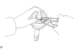
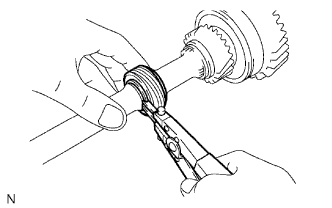
Using a snap ring expander, install the snap ring.
-
-
INSPECT 3RD GEAR THRUST CLEARANCE
-
Using a feeler gauge, measure the thrust clearance.
Standard clearance 0.10 to 0.25 mm (0.0039 to 0.0098in.)
-
-
INSTALL NO. 1 TRANSMISSION CLUTCH HUB
-
Coat the reverse gear with gear oil, and install it to the clutch hub.
Note
Be sure to set the reverse gear to the clutch hub in the correct direction.
-
Install 3 synchromesh shifting keys to the clutch hub with the 2 synchromesh shifting key springs.
Tech Tips
Do not set both openings of the shifting key springs in the same position.
-
-
INSTALL 2ND GEAR NEEDLE ROLLER BEARING
-
Coat the needle roller bearing with gear oil, and install it to the output shaft.
-
-
INSTALL 2ND GEAR
-
Coat the 2nd gear with gear oil, and install it to the output shaft.
-
-
INSTALL NO. 1 SYNCHRONIZER RING (for 2nd Gear)
-
Coat the No. 1 synchronizer ring with gear oil, and install it to the 2nd gear.
-
-
INSTALL NO. 1 TRANSMISSION CLUTCH HUB
-
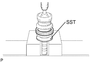
Using SST and a press, press in the clutch hub to the output shaft.
- SST
- 09316-60011
-
-
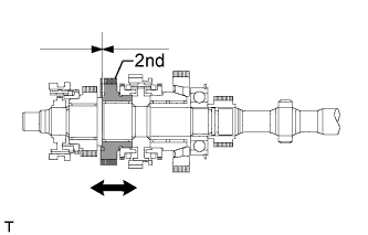
INSPECT 2ND GEAR THRUST CLEARANCE
-
Using a dial indicator, measure the thrust clearance.
Standard clearance 0.10 to 0.250 mm (0.0039 to 0.0098 in.)
-
-
INSTALL NO. 1 SYNCHRONIZER RING (for 1st Gear)
-
Coat the synchronizer ring with gear oil, and install it to the No. 1 clutch hub.
-
-
INSTALL 1ST GEAR BEARING INNER RACE LOCK BALL
-
Coat the lock ball with gear oil, and install it to the output shaft.
-
-
INSTALL 1ST GEAR BEARING INNER RACE
-
Coat the needle roller bearing with gear oil.
-
Install the inner race and the needle roller bearing to the 1st gear.
-
-
INSTALL 1ST GEAR
-
Coat the 1st gear with gear oil, and install it to the output shaft.
-
-
INSTALL OUTPUT SHAFT CENTER BEARING
-
Using SST and a press, press in the center bearing to the output shaft.
- SST
- 09316-60011 ( 09316-00021 )
-
-
INSPECT 1ST GEAR THRUST CLEARANCE
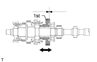
-
Using a dial indicator, measure the thrust clearance.
Standard clearance 0.10 to 0.25 mm (0.0039 to 0.0078 in.)
-
-
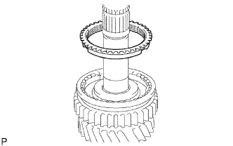
INSTALL 5TH GEAR
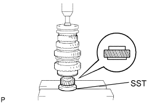
-
Using SST and a press, press in the 5th gear to the output shaft.
- SST
- 09316-60011 ( 09316-00021 )
-
Select a snap ring that will allow minimal axial play.
Standard clearance 0.10 mm (0.039 in.) or less Standard output shaft bearing shaft snap ring Mark Thickness A 2.67 to 2.72 mm (0.1051 to 0.1071 in.) B 2.73 to 2.78 mm (0.1075 to 0.1094 in.) C 2.79 to 2.84 mm (0.1098 to 0.1118 in.) D 2.85 to 2.90 mm (0.1122 to 0.1141 in.) E 2.91 to 2.96 mm (0.1146 to 0.1165 in.) F 2.97 to 3.02 mm (0.1169 to 0.1189 in.) G 3.03 to 3.08 mm (0.1193 to 0.1213 in.) H 3.09 to 3.14 mm (0.1217 to 0.1236 in.) J 3.15 to 3.20 mm (0.1240 to 0.1260 in.) K 3.21 to 3.26 mm (0.1264 to 0.1283 in.) L 3.27 to 3.32 mm (0.1287 to 0.1307 in.) -
Using a screwdriver and hammer, tap in the snap ring.
-
-
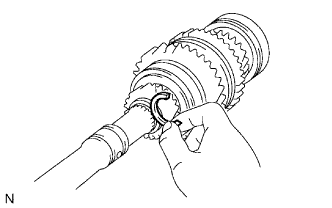
INSTALL SPEEDOMETER DRIVE GEAR
-
Using a snap ring expander, install the snap ring.
-
Install the ball.
-
Install the drive gear.
-
Using a snap ring expander, install the snap ring.
-
-
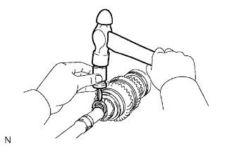
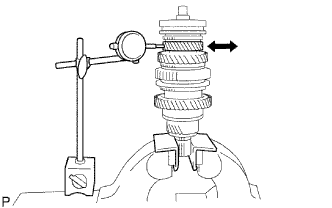
INSPECT 3RD GEAR RADIAL CLEARANCE
-
Using a dial indicator, measure the radial clearance.
Standard clearance 0.008 to 0.034 mm (0.0003 to 0.0013 in.)
-
If the clearance is not as specified, replace the needle roller bearing.
-
-
-
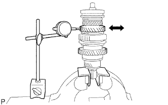
INSPECT 2ND GEAR RADIAL CLEARANCE
-
Using a dial indicator, measure the radial clearance.
Standard clearance 0.008 to 0.034 mm (0.0003 to 0.0013 in.)
-
If the clearance is not as specified, replace the needle roller bearing.
-
-
-
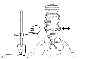
INSPECT 1ST GEAR RADIAL CLEARANCE
-
Using a dial indicator, measure the radial clearance.
Standard clearance 0.009 to 0.056 mm (0.0004 to 0.0022 in.)
-
If the clearance is not as specified, replace the needle roller bearing.
-
-