INTAKE SYSTEM
-
CONSTRUCTION
-
A turbocharger sub-assembly is used to achieve high engine output, high torque and low emissions.
-
An efficient twin-scroll turbocharger is used in the turbocharger sub-assembly to prevent exhaust interference between cylinders and achieve high engine output and to high torque over all ranges from low to high engine speeds.
-
A wastegate valve is used in the turbocharger sub-assembly. When the vehicle is being driven at low load (boost is not necessary), the wastegate valve opens to decrease the back pressure and reduce pumping losses during the exhaust stroke. Also, the wastegate valve opens during start-up to decrease the amount of time needed for the catalyst to warm up.
-
The wastegate valve opens downwards to introduce high temperature gas directly to the Three-Way Catalytic converter (TWC). As a result, TWC warm-up performance during start-up and exhaust gas purification performance are enhanced.
Tech Tips
When starting the engine, sound is generated near the wastegate valve that is used to quickly warm up the catalyst, but this is not a malfunction of the turbocharger. When engine warm-up is complete, sound is no longer generated.
-
An electric air bypass valve is used in the turbocharger sub-assembly to prevent the surge phenomenon* from occurring. When the throttle valve closes with the accelerator pedal released, the pressure between the turbocharger sub-assembly and throttle valve increases. This pressure is diverted upstream of the turbocharger sub-assembly when the air bypass valve opens.
Tech Tips
*: Surge phenomenon: This phenomenon occurs when the intake airflow reverses. As a result, an abnormal noise is generated during deceleration.
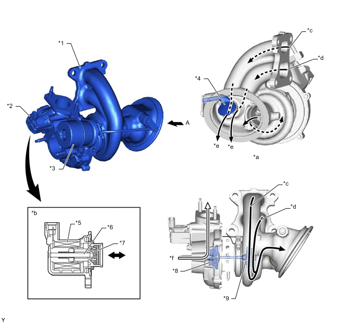
*1 Turbocharger Sub-assembly *2 Air Bypass Valve *3 Actuator *4 Wastegate Valve *5 Coil *6 Shaft *7 Valve *8 Compressor Wheel *9 Turbine Wheel - - *a View from A *b Air Bypass Valve Cross Section *c Exhaust Gas (from No. 2 and No. 3 Cylinders) *d Exhaust Gas (from No. 1 and No. 4 Cylinders) *e Bypass Gas *f Intake Air
-
-
OPERATION
-
Wastegate Valve
-
When the engine is stopped, the wastegate valve is open.
-
When the vacuum regulating valve assembly cuts the vacuum to the actuator according to signals from the ECM, the actuator opens the wastegate valve through a link.
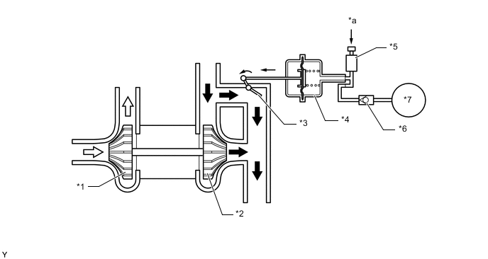
*1 Compressor Wheel *2 Turbine Wheel *3 Wastegate Valve *4 Actuator *5 Vacuum Regulating Valve Assembly *6 No. 2 Check Valve *7 Vacuum Pump Assembly - - *a From ECM - - 
Exhaust Gas 
Intake Air -
When the vacuum regulating valve assembly applies a vacuum to the actuator according to signals from the ECM, the actuator closes the wastegate valve through a link.
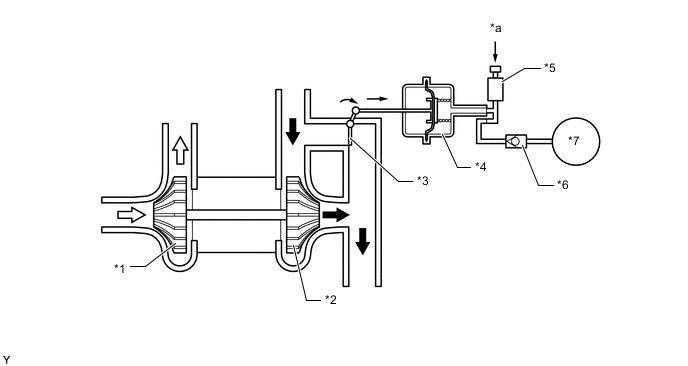
*1 Compressor Wheel *2 Turbine Wheel *3 Wastegate Valve *4 Actuator *5 Vacuum Regulating Valve Assembly *6 No. 2 Check Valve *7 Vacuum Pump Assembly - - *a From ECM - - Exhaust Gas Intake Air -
The amount of vacuum applied is determined by the opening angle of the wastegate valve.
-
-
Air Bypass Valve
-
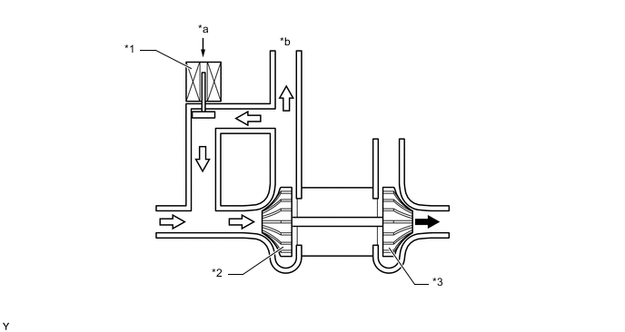
The air bypass valve opens according to signals from the ECM to divert the pressure between the turbocharger sub-assembly and throttle valve, which is increased when the throttle valve is closed, upstream of the turbocharger sub-assembly.
Figure 1. Air Bypass Valve Closed
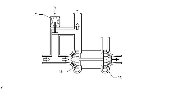
*1 Air Bypass Valve *2 Compressor Wheel *3 Turbine Wheel - - *a From ECM *b To Throttle Body with Motor Assembly Exhaust Gas Intake Air Figure 2. Air Bypass Valve Open
*1 Air Bypass Valve *2 Compressor Wheel *3 Turbine Wheel - - *a From ECM *b To Throttle Body with Motor Assembly Exhaust Gas Intake Air
-
-