CYLINDER BLOCK INSPECTION
PROCEDURE
CLEAN CYLINDER BLOCK SUB-ASSEMBLY
Using a gasket scraper, remove all the gasket material from the top surface of the cylinder block.
Using a soft brush and solvent, thoroughly clean the cylinder block.
Note:If the cylinder is washed at high temperatures, the cylinder liner sticks out beyond the cylinder block. Always wash the cylinder block at a temperature of 45°C (113°F) or less.
INSPECT CYLINDER BLOCK FOR WARPAGE
-
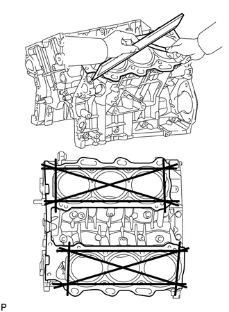
Using a precision straightedge and feeler gauge, measure the warpage of the surfaces which contact the cylinder head gaskets.
Maximum warpage
0.05 mm (0.00197 in.)
If the warpage is more than the maximum, replace the cylinder block.
Visually check the cylinder for vertical scratches.
If deep scratches are present, replace the cylinder block.
-
INSPECT CYLINDER BORE
-
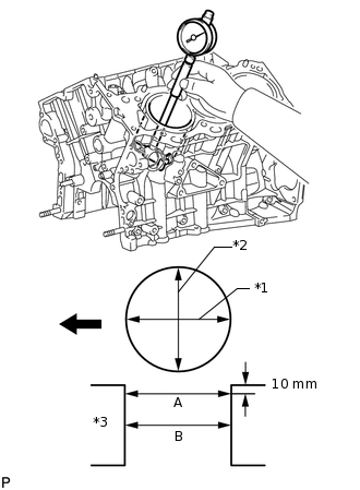
*1
Axial Direction
*2
Thrust Direction
*3
Center

Engine Front
Using a cylinder gauge, measure the cylinder bore diameter at positions A and B in the thrust and axial directions.
Standard diameter
94.000 to 94.012 mm (3.7008 to 3.7013 in.)
Maximum diameter
94.132 mm (3.7060 in.)
Measurement position (A)
10 mm (0.394 in.)
If the diameter is more than the maximum, replace the cylinder block.
-
INSPECT RING GROOVE CLEARANCE
Using a feeler gauge, measure the clearance between a new piston ring and the wall of the ring groove.
Standard Ring Groove Clearance
Item
Specified Condition
No. 1 compression ring
0.02 to 0.07 mm (0.000787 to 0.00276 in.)
No. 2 compression ring
0.02 to 0.06 mm (0.000787 to 0.00236 in.)
Oil Ring
0.07 to 0.15 mm (0.00276 to 0.00590 in.)
If the clearance is not as specified, replace the piston with pin sub-assembly.
INSPECT PISTON RING END GAP
Insert the piston ring into the cylinder bore.
Using a piston, push the piston ring a little beyond the bottom of the ring travel, 110 mm (4.33 in.) from the top of the cylinder block.
Using a feeler gauge, measure the end gap.
Standard End Gap
Item
Specified Condition
No. 1 compression ring
0.22 to 0.32 mm (0.00866 to 0.0126 in.)
No. 2 compression ring
0.35 to 0.45 mm (0.0138 to 0.0177 in.)
Oil ring (side rail)
0.10 to 0.40 mm (0.00394 to 0.0157 in.)
Maximum End Gap
Item
Specified Condition
No. 1 compression ring
1.0 mm (0.0394 in.)
No. 2 compression ring
1.1 mm (0.0433 in.)
Oil ring (side rail)
1.0 mm (0.0394 in.)
If the end gap is more than the maximum, replace the piston ring. If the end gap is more than the maximum even with a new piston ring, replace the cylinder block sub-assembly.
CLEAN PISTON WITH PIN SUB-ASSEMBLY
Using a gasket scraper, remove the carbon from the piston top.
Using a groove cleaning tool or broken ring, clean the piston ring grooves.
Using solvent and a brush, thoroughly clean the piston.
Note:Do not use a wire brush.
INSPECT PISTON OIL CLEARANCE
-
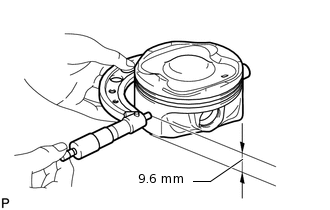
Using a micrometer, measure the piston diameter at a position that is 9.6 mm (0.378 in.) from the bottom of the piston (refer to the illustration).
Piston diameter
93.961 to 93.991 mm (3.6992 to 3.7004 in.)
Subtract the piston diameter measurement from the cylinder bore diameter measurement.
Standard oil clearance
0.009 to 0.051 mm (0.000354 to 0.00201 in.)
Maximum oil clearance
0.110 mm (0.00433 in.)
If the oil clearance is more than the maximum, replace all 6 pistons. If necessary, replace the cylinder block.
-
INSPECT PISTON PIN OIL CLEARANCE
-
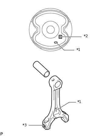
*1
Front Mark
*2
Position Pin Hole Inside Diameter Mark
*3
Connecting Rod Bush Inside Diameter Mark
Check each mark on the piston and connecting rod.
-
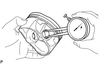
Using a caliper gauge, measure the inside diameter of the piston pin hole.
Standard Piston Pin Hole Inside Diameter
Item
Specified Condition
Mark A
22.001 to 22.004 mm (0.86618 to 0.86630 in.)
Mark B
22.005 to 22.007 mm (0.86634 to 0.86642 in.)
Mark C
22.008 to 22.010 mm (0.86645 to 0.86653 in.)
-
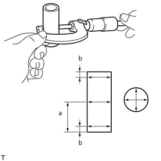
Using a micrometer, measure the piston pin diameter.
Measurement Position
Measurement Position
Piston Pin Position
a
28 mm (1.102 in.) from edge
b
5 mm (0.197 in.) from edge
Standard Piston Pin Diameter
Item
Specified Condition
Mark A
21.997 to 22.000 mm (0.86602 to 0.86614 in.)
Mark B
22.001 to 22.003 mm (0.86618 to 0.86626 in.)
Mark C
22.004 to 22.006 mm (0.86630 to 0.86642 in.)
Using a caliper gauge, measure the inside diameter of the connecting rod bush.
Standard Bush Inside Diameter
Item
Specified Condition
Mark A
22.005 to 22.008 mm (0.86634 to 0.86645 in.)
Mark B
22.009 to 22.011 mm (0.86649 to 0.86657 in.)
Mark C
22.012 to 22.014 mm (0.86661 to 0.86669 in.)
Subtract the piston pin diameter measurement from the piston pin hole diameter measurement.
Standard oil clearance
0.001 to 0.007 mm (0.0000394 to 0.000276 in.)
Maximum oil clearance
0.040 mm (0.00157 in.)
If the oil clearance is more than the maximum, replace the piston with pin sub-assembly.
Subtract the piston pin diameter measurement from the bush inside diameter measurement.
Standard oil clearance
0.005 to 0.011 mm (0.000197 to 0.000433 in.)
Maximum oil clearance
0.050 mm (0.00197 in.)
If the oil clearance is more than the maximum, replace the connecting rod small end bush. If necessary, replace the connecting rod sub-assembly and piston with pin sub-assembly.
-
INSPECT CONNECTING ROD SUB-ASSEMBLY
-
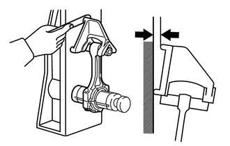
Using a rod aligner and feeler gauge, check the connecting rod alignment.
Check for bend.
Maximum bend
0.05 mm (0.00197 in.) per 100 mm (3.94 in.)
If the bend is more than the maximum, replace the connecting rod sub-assembly.
-
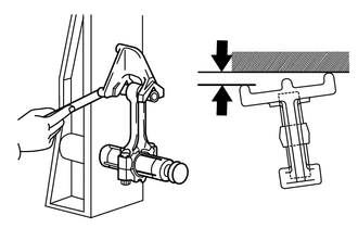
Check for twist.
Maximum twist
0.15 mm (0.00591 in.) per 100 mm (3.94 in.)
If the twist is more than the maximum, replace the connecting rod sub-assembly.
-
INSPECT CRANKSHAFT
Using a dial indicator, measure the runout at the center journal.
Maximum circle runout
0.06 mm (0.00236 in.)
If the circle runout is more than the maximum, replace the crankshaft.
-
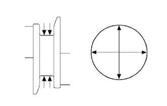
Using a micrometer, measure the diameter of each main journal.
Standard diameter
71.988 to 72.000 mm (2.8342 to 2.8346 in.)
If the diameter is not as specified, check the oil clearance. If necessary, replace the crankshaft.
Check each main journal for taper and out-of-round as shown in the illustration.
Maximum taper and out-of-round
0.02 mm (0.000787 in.)
If the taper and out-of-round is more than the maximum, replace the crankshaft.
-
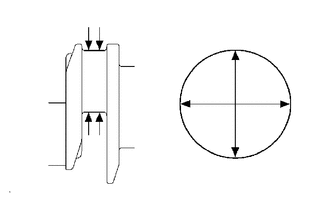
Using a micrometer, measure the diameter of each crank pin.
Standard diameter
55.992 to 56.000 mm (2.2044 to 2.2047 in.)
If the diameter is not as specified, check the oil clearance. If necessary, replace the crankshaft.
Check each crank pin for taper and out-of-round as shown in the illustration.
Maximum taper and out-of-round
0.02 mm (0.000787 in.)
If the taper and out-of-round is more than the maximum, replace the crankshaft.
INSPECT CONNECTING ROD BOLT
-
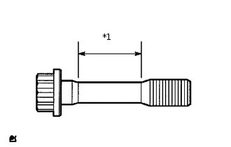
*1
Measurement Area
Using a vernier caliper, measure the tension portion diameter of the bolt.
Standard diameter
7.2 to 7.3 mm (0.283 to 0.287 in.)
Minimum diameter
7.0 mm (0.276 in.)
If the diameter is less than the minimum, replace the connecting rod bolt.
-
INSPECT CRANKSHAFT BEARING CAP SET BOLT
-
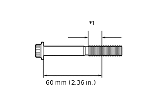
*1
Measurement Area
Using a vernier caliper, measure the thread outside diameter of the crankshaft bearing cap set bolt.
Standard diameter
10.0 to 10.2 mm (0.394 to 0.402 in.)
If the result is not as specified, replace the crankshaft bearing cap set bolt.
-
INSPECT CRANKSHAFT OIL CLEARANCE
Install the crankshaft oil bearing (Click here).
Place the crankshaft on the cylinder block.
-
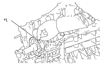
*1
Plastigage
Lay a strip of Plastigage across each journal.
Install the crankshaft bearing cap (Click here).
Note:Do not turn the crankshaft.
Remove the crankshaft bearing cap (Click here).
-
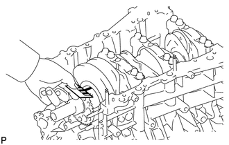
Measure the Plastigage at its widest point.
Standard oil clearance
0.026 to 0.046 mm (0.00102 to 0.00181 in.)
Maximum clearance
0.080 mm (0.00315 in.)
If the oil clearance is more than the maximum, replace the bearings. If necessary, replace the crankshaft.
-
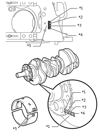
*1
No. 1
*2
No. 2
*3
No. 3
*4
No. 4
*5
Number Mark
If replacing a bearing, replace it with one that has the same number. If the number of the bearing cannot be determined, select the correct bearing by adding together the numbers imprinted on the cylinder block and crankshaft, and then refer to the table below for the appropriate bearing number. There are 5 sizes of standard bearings, marked "1", "2", "3", "4" and "5" accordingly.
Chart Bearing
Item
Specified Condition
Cylinder block main journal bore diameter (A)
+
Crankshaft main journal diameter (B)
0 to 5
6 to 11
12 to 17
18 to 23
24 to 28
Use bearing
1
2
3
4
5
EXAMPLE:
Cylinder block "11" (A) + Crankshaft "06" (B) = Total number 17 (Use bearing "3")
Standard Cylinder Block Main Journal Bore Diameter (A)
Mark
Specified Condition
Mark 00
77.000 mm (3.03149 in.)
Mark 01
77.001 mm (3.03152 in.)
Mark 02
77.002 mm (3.03156 in.)
Mark 03
77.003 mm (3.03160 in.)
Mark 04
77.004 mm (3.03164 in.)
Mark 05
77.005 mm (3.03168 in.)
Mark 06
77.006 mm (3.03172 in.)
Mark 07
77.007 mm (3.03176 in.)
Mark 08
77.008 mm (3.03180 in.)
Mark 09
77.009 mm (3.03184 in.)
Mark 10
77.010 mm (3.03188 in.)
Mark 11
77.011 mm (3.03192 in.)
Mark 12
77.012 mm (3.03196 in.)
Mark 13
77.013 mm (3.03200 in.)
Mark 14
77.014 mm (3.03204 in.)
Mark 15
77.015 mm (3.03208 in.)
Mark 16
77.016 mm (3.03211 in.)
Standard Crankshaft Main Journal Diameter (B)
Item
Specified Condition
Mark 00
71.999 to 72.000 mm (2.83460 to 2.83464 in.)
Mark 01
71.998 to 71.999 mm (2.83456 to 2.83460 in.)
Mark 02
71.997 to 71.998 mm (2.83452 to 2.83456 in.)
Mark 03
71.996 to 71.997 mm (2.83448 to 2.83452 in.)
Mark 04
71.995 to 71.996 mm (2.83440 to 2.83448 in.)
Mark 05
71.994 to 71.995 mm (2.83440 to 2.83444 in.)
Mark 06
71.993 to 71.994 mm (2.83436 to 2.83440 in.)
Mark 07
71.992 to 71.993 mm (2.83432 to 2.83436 in.)
Mark 08
71.991 to 71.992 mm (2.83428 to 2.83432 in.)
Mark 09
71.990 to 71.991 mm (2.83424 to 2.83428 in.)
Mark 10
71.989 to 71.990 mm (2.83420 to 2.83424 in.)
Mark 11
71.988 to 71.989 mm (2.83416 to 2.83420 in.)
Standard Bearing Center Wall Thickness
Item
Specified Condition
Mark 1
2.488 to 2.491 mm (0.0980 to 0.0981 in.)
Mark 2
2.491 to 2.494 mm (0.0981 to 0.0982 in.)
Mark 3
2.494 to 2.497 mm (0.0982 to 0.0983 in.)
Mark 4
2.497 to 2.500 mm (0.0983 to 0.0984 in.)
Mark 5
2.500 to 2.503 mm (0.0984 to 0.0985 in.)
Perform the inspection above for each journal.
Completely remove the Plastigage.
INSPECT NO. 1 OIL NOZZLE SUB-ASSEMBLY
-
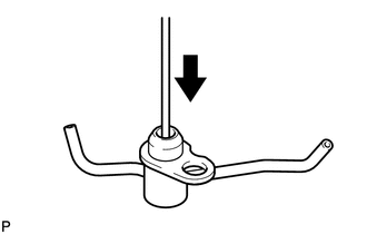
Push the check valve with a pin to check if it is stuck. If stuck, replace the oil nozzle.
Push the check valve with a pin to check if it moves smoothly.
If it does not move smoothly, clean or replace the oil nozzle.
-
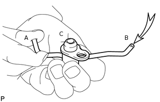
While covering A, blow air into B. Check that air does not leak through C. Perform the check again while covering B and blowing air into A.
If air leaks, clean or replace the oil nozzle.
-
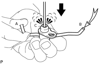
Push the check valve while covering A, and blow air into B. Check that air passes through C. Perform the check again while covering B, pushing the check valve and blowing air into A.
If air does not pass through C, clean or replace the oil nozzle.
-