REAR SEAT ENTERTAINMENT SYSTEM, Diagnostic DTC:B15CE
| DTC Code | DTC Name |
|---|---|
| B15CE | Seatback Display Disconnected |
DESCRIPTION
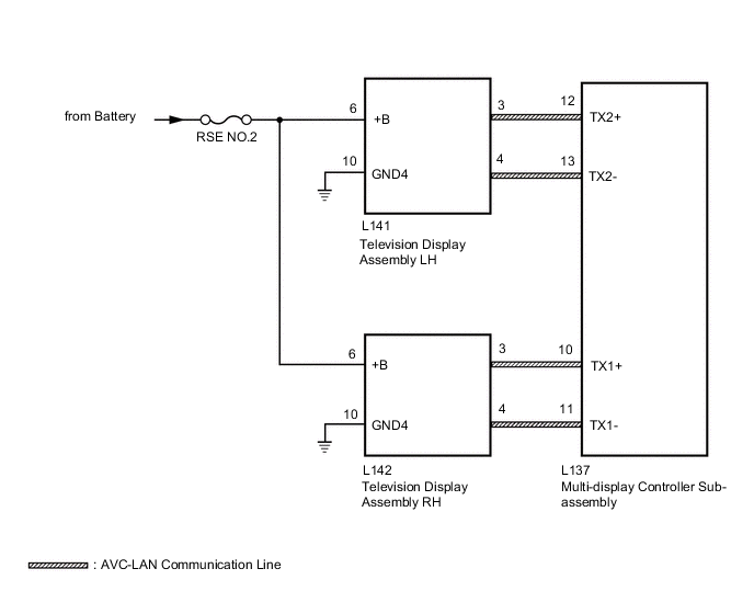
The television display assemblies and multi-display controller sub-assembly are connected via AVC-LAN communication.
This DTC will be stored if an AVC-LAN communication error occurs between the multi-display controller sub-assembly and a television display assembly.
| DTC No. | Detection Item | DTC Detection Condition | Trouble Area |
|---|---|---|---|
| B15CE | Seatback Display Disconnected | Seatback Display Disconnected |
|
WIRING DIAGRAM
CAUTION / NOTICE / HINT
Note
Inspect the fuses and relays for circuits related to this system before performing the following procedure.
PROCEDURE
-
CLEAR DTC
-
Clear the DTCs.
Body Electrical > Navigation System > Clear DTCsResult Proceed to NEXT
NEXT 
-
-
CHECK FOR DTC
-
Check for DTCs.
Body Electrical > Navigation System > Trouble CodesOK No DTCs are output. Result Proceed to OK NG
OK 
USE SIMULATION METHOD TO CHECK Click here
NG
-
-
CHECK OPERATION
-
Check which television display assembly does not operate.
Result Result Proceed to Television display assembly LH does not operate. A Television display assembly RH does not operate. B
B 
CHECK HARNESS AND CONNECTOR (TELEVISION DISPLAY ASSEMBLY RH - BATTERY AND BODY GROUND) Click here
A
-
-
CHECK HARNESS AND CONNECTOR (TELEVISION DISPLAY ASSEMBLY LH - BATTERY AND BODY GROUND)
-
Disconnect the L141 television display assembly LH connector.
-
Measure the resistance according to the value(s) in the table below.
Standard Resistance: Tester Connection Condition Specified Condition L141-10 (GND4) - Body ground Always Below 1 Ω -
Measure the voltage according to the value(s) in the table below.
Standard Voltage: Tester Connection Condition Specified Condition L141-6 (+B) - L141-10 (GND4) Always 11 to 14 V Result Proceed to OK NG
NG
REPAIR OR REPLACE HARNESS OR CONNECTOR
OK
-
-
CHECK HARNESS AND CONNECTOR (MULTI-DISPLAY CONTROLLER SUB-ASSEMBLY - TELEVISION DISPLAY ASSEMBLY LH)
-
Disconnect the L137 multi-display controller sub-assembly connector.
-
Disconnect the L141 television display assembly LH connector.
-
Measure the resistance according to the value(s) in the table below.
Standard Resistance: Tester Connection Condition Specified Condition L137-12 (TX2+) - L141-3 Always Below 1 Ω L137-13 (TX2-) - L141-4 Always Below 1 Ω L137-12 (TX2+) - Body ground Always 10 kΩ or higher L137-13 (TX2-) - Body ground Always 10 kΩ or higher Result Proceed to OK NG
NG
REPAIR OR REPLACE HARNESS OR CONNECTOR
OK
-
-
REPLACE TELEVISION DISPLAY ASSEMBLY LH
-
Replace the television display assembly LH.
Result Proceed to NEXT
NEXT
-
-
CLEAR DTC
-
Clear the DTCs.
Body Electrical > Navigation System > Clear DTCsResult Proceed to NEXT
NEXT
-
-
CHECK FOR DTC
-
Check for DTCs.
Body Electrical > Navigation System > Trouble CodesOK No DTCs are output. Result Proceed to OK NG
OK
END (TELEVISION DISPLAY ASSEMBLY LH IS DEFECTIVE)
NG
REPLACE MULTI-DISPLAY CONTROLLER SUB-ASSEMBLY Click here
-
-
CHECK HARNESS AND CONNECTOR (TELEVISION DISPLAY ASSEMBLY RH - BATTERY AND BODY GROUND)
-
Disconnect the L142 television display assembly RH connector.
-
Measure the resistance according to the value(s) in the table below.
Standard Resistance: Tester Connection Condition Specified Condition L142-10 (GND4) - Body ground Always Below 1 Ω -
Measure the voltage according to the value(s) in the table below.
Standard Voltage: Tester Connection Condition Specified Condition L142-6 (+B) - L142-10 (GND4) Always 11 to 14 V Result Proceed to OK NG
NG
REPAIR OR REPLACE HARNESS OR CONNECTOR
OK
-
-
CHECK HARNESS AND CONNECTOR (MULTI-DISPLAY CONTROLLER SUB-ASSEMBLY - TELEVISION DISPLAY ASSEMBLY RH)
-
Disconnect the L137 multi-display controller sub-assembly connector.
-
Disconnect the L142 television display assembly RH connector.
-
Measure the resistance according to the value(s) in the table below.
Standard Resistance: Tester Connection Condition Specified Condition L137-10 (TX1+) - L142-3 Always Below 1 Ω L137-11 (TX1-) - L142-4 Always Below 1 Ω L137-10 (TX1+) - Body ground Always 10 kΩ or higher L137-11 (TX1-) - Body ground Always 10 kΩ or higher Result Proceed to OK NG
NG
REPAIR OR REPLACE HARNESS OR CONNECTOR
OK
-
-
REPLACE TELEVISION DISPLAY ASSEMBLY RH
-
Replace the television display assembly RH.
Result Proceed to NEXT
NEXT
-
-
CLEAR DTC
-
Clear the DTCs.
Body Electrical > Navigation System > Clear DTCsResult Proceed to NEXT
NEXT
-
-
CHECK FOR DTC
-
Check for DTCs.
Body Electrical > Navigation System > Trouble CodesOK No DTCs are output. Result Proceed to OK NG
OK
END (TELEVISION DISPLAY ASSEMBLY RH IS DEFECTIVE)
NG
REPLACE MULTI-DISPLAY CONTROLLER SUB-ASSEMBLY Click here
-