VEHICLE STABILITY CONTROL SYSTEM, Diagnostic DTC:C1252
| DTC Code | DTC Name |
|---|---|
| C1252 | Brake Booster Pump Motor on Time Abnormally Long |
DESCRIPTION
The motor relay (semiconductor relay) is built into the master cylinder solenoid and drives the pump motor based on a signal from the skid control ECU.
DTC No. |
Detection Item |
DTC Detection Condition |
Trouble Area |
|---|---|---|---|
C1252 |
Brake Booster Pump Motor on Time Abnormally Long |
The motor operates for 3 minutes or more. |
|
The pump motor continues operation for the first 3 minutes, and then starts and stops repeatedly.
CAUTION / NOTICE / HINT
When replacing the master cylinder solenoid, perform calibration (Click here).
When DTC C1253, C1254, C1256 or C1452 is output together with DTC C1252, inspect and repair the trouble area indicated by DTC C1253, C1254, C1256 or C1452 first.
PROCEDURE
CHECK PUMP MOTOR OPERATION
Turn the engine switch off.
Depress the brake pedal more than 40 times.
Turn the engine switch on (IG).
Check how the pump motor operates.
Result
Result
Proceed to
Pump motor does not operate
A
Pump motor operates continuously and does not stop
B
Pump motor operates intermittently
C
Pump motor operates, and then stops
D
CHECK CONNECTION OF PUMP MOTOR WIRE HARNESS
Remove the hydraulic brake booster assembly.
Check the tightening torque of the 2 screws which secure the wire harness connecting the master cylinder solenoid and brake booster with accumulator pump assembly.
OK
The harness is tightened to the specified torque.
Torque
2.9 N*m{ 30 kgf*cm , 26 in.*lbf }
Result
Result
OK
NG
NG RETIGHTEN SCREWS
CHECK RESISTANCE OF PUMP MOTOR WIRE HARNESS
Using a screwdriver, remove the 2 screws and pull out the wire harness from the master cylinder solenoid.
-
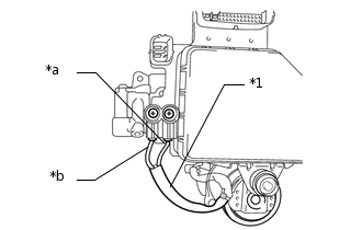
*1
Pump motor wire harness
*a
Red wire
*b
Black wire
Measure the resistance according to the value(s) in the table below.
Standard Resistance
Tester Connection
Condition
Specified Condition
Red wire terminal - Black wire terminal
Always
Below 2 Ω
Result
Result
OK
NG
READ VALUE USING INTELLIGENT TESTER (ACCUMULATOR SENSOR)
Turn the engine switch off.
Connect the intelligent tester to the DLC3.
Turn the engine switch on (IG).
Turn the intelligent tester on.
Enter the following menus: Chassis / ABS/VSC/TRC / Data List.
Chassis > ABS/VSC/TRC > Data List
Tester Display
Measurement Item
Range
Normal Condition
Diagnostic Note
Accumulator Sensor
Accumulator pressure sensor reading
Min.: 0.00 V, Max.: 5.00 V
3.58 to 5 V
If the value is constant regardless of the pump operation, an accumulator pressure sensor malfunction is suspected.
Check the accumulator output value.
Result
Result
Proceed to
Output value is within "Normal Condition" range
A
Output value is out of "Normal Condition" range
B
Output value is constant regardless of pump operation
C
RECONFIRM DTC
Clear the DTCs.
Chassis > ABS/VSC/TRC > Clear DTCs
Turn the engine switch off.
Turn the engine switch on (IG).
Wait for more than 5 minutes.
Check if the same DTC is output.
Result
Result
Proceed to
DTC is output
A
DTC is not output
B
Tip:Reinstall the sensors, reconnect the connectors, etc. and restore the previous vehicle conditions before rechecking for DTCs.
Chassis > ABS/VSC/TRC > Trouble Codes