CAMSHAFT INSTALLATION
PROCEDURE
INSTALL OIL CONTROL VALVE FILTER
TEMPORARILY INSTALL CAMSHAFT TIMING SPROCKET ASSEMBLY
-
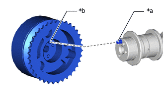
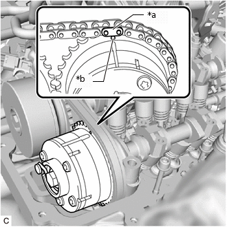
*a
Straight Pin
*b
Straight Pin Hole
Fit the camshaft timing sprocket assembly and camshaft together with the straight pin and straight pin hole aligned as shown in the illustration.
Temporarily install the camshaft timing sprocket assembly with the bolt.
Make sure that the camshaft timing sprocket assembly gear is locked.
-
INSTALL CAMSHAFT
-
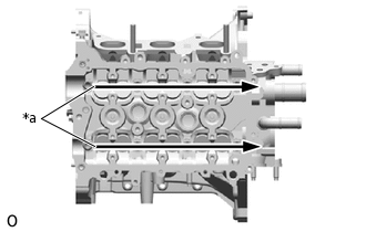
*a
Apply engine oil
Apply engine oil to the cams of each camshaft, the journals of the cylinder head sub-assembly and the top of each valve lifter.
-
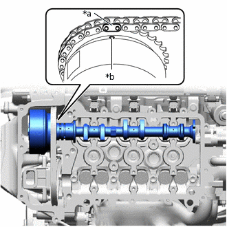
*a
Paint Mark
*b
Timing Mark
Align the paint mark of the timing chain plate with the timing mark of the camshaft timing sprocket assembly and install the chain sub-assembly.
-
INSTALL NO. 2 CAMSHAFT
Set the No. 2 camshaft onto the cylinder head sub-assembly.
-
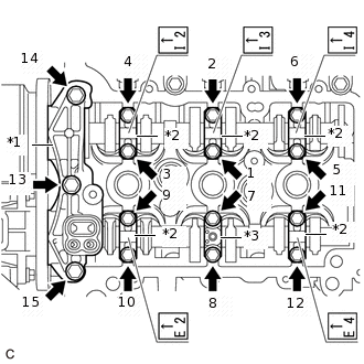
*1
No. 1 Camshaft Bearing Cap
*2
No. 2 Camshaft Bearing Cap
*3
No. 3 Camshaft Bearing Cap
Place the No. 1 camshaft bearing cap, 5 No. 2 camshaft bearing caps and No. 3 camshaft bearing cap and tighten the bolts with the specified torque in the order shown in the illustration.
No. 1 Camshaft Bearing Cap
15 N*m
153 kgf*cm
11 ft.*lbf
No. 2 Camshaft Bearing Cap and No. 3 Camshaft Bearing Cap
12.5 N*m
127 kgf*cm
9 ft.*lbf
Note:Install the No. 1 camshaft bearing cap and 5 No. 2 camshaft bearing caps with the front marks facing the front of the engine.
INSTALL CAMSHAFT TIMING EXHAUST GEAR ASSEMBLY
-
*a
Paint Mark
*b
Timing Mark
Align the paint mark of the chain plate with the timing mark of the camshaft timing exhaust gear assembly and install the chain sub-assembly.
Install the camshaft timing exhaust gear assembly to the No. 2 camshaft with the knock pin aligned with the pin hole.
-
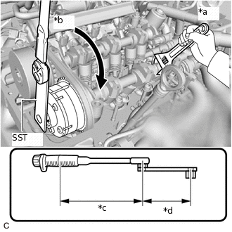
*a
Hold
*b
Turn
*c
Torque wrench with a fulcrum length of 260 mm (10.24 in.)
*d
SST with a fulcrum length of 100 mm (3.94 in.)
Using a wrench to hold the hexagonal portion of the No. 2 camshaft, install the bolt using SST.
09249-37010
without SST
54 N*m
551 kgf*cm
40 ft.*lbf
with SST
39 N*m
398 kgf*cm
29 ft.*lbf
Tip:This torque value is effective when SST is parallel to the torque wrench.
The "with SST" torque value is effective when using SST with a fulcrum length of 100 mm (3.94 in.).
The "with SST" torque value is effective when using a torque wrench with a fulcrum length of 260 mm (10.24 in.).
If using a torque wrench with a different length, or connecting the torque wrench and SST at an angle, refer to the alternate torque values.
-
TIGHTEN CAMSHAFT TIMING SPROCKET ASSEMBLY
-
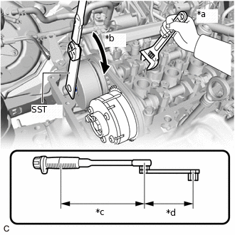
*a
Hold
*b
Turn
*c
Torque wrench with a fulcrum length of 260 mm (10.24 in.)
*d
SST with a fulcrum length of 100 mm (3.94 in.)
Using a wrench to hold the hexagonal portion of the camshaft, install the bolt using SST.
09249-37010
without SST
54 N*m
551 kgf*cm
40 ft.*lbf
with SST
39 N*m
398 kgf*cm
29 ft.*lbf
Tip:This torque value is effective when SST is parallel to the torque wrench.
The "with SST" torque value is effective when using SST with a fulcrum length of 100 mm (3.94 in.).
The "with SST" torque value is effective when using a torque wrench with a fulcrum length of 260 mm (10.24 in.).
If using a torque wrench with a different length, or connecting the torque wrench and SST at an angle, refer to the alternate torque values.
-
INSTALL BRACKET
INSTALL TIMING GEAR COVER TIGHT PLUG
Remove the hexagon wrench from the No. 1 chain tensioner assembly.
-
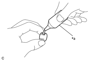
*a
Adhesive 1324
Clean the timing gear cover tight plug and the bolt holes of the timing chain cover sub-assembly and apply adhesive to the threads of the timing gear cover tight plug.
Adhesive
Toyota Genuine Adhesive 1324, Three Bond 1324 or equivalent
Using an 8 mm hexagon socket wrench, install the timing gear cover tight plug.
15 N*m
153 kgf*cm
11 ft.*lbf
Note:Do not start the engine for at least 1 hour after installation.
INSPECT VALVE CLEARANCE
ADJUST VALVE CLEARANCE
INSTALL CYLINDER HEAD COVER GASKET
INSTALL CYLINDER HEAD COVER SUB-ASSEMBLY
INSTALL CAMSHAFT TIMING OIL CONTROL VALVE ASSEMBLY (for Exhaust Side)
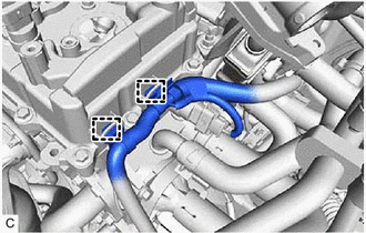
CONNECT OIL LEVEL GAUGE GUIDE OIL HOSE
Connect the oil hose to the cylinder head cover sub-assembly and slide the clip to secure it.
CONNECT ENGINE WIRE
-

Connect the heated oxygen sensor connector.
Engage the clamp.
-
Engage the 2 clamps.
-
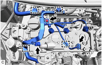
Install the nut.
8.4 N*m
86 kgf*cm
74 in.*lbf
Engage the 4 clamps.
Connect the camshaft position sensor connector and cam timing oil control valve assembly.
-
INSTALL NO. 1 IGNITION COIL
INSTALL AIR CLEANER CASE SUB-ASSEMBLY
INSTALL AIR CLEANER FILTER ELEMENT SUB-ASSEMBLY
INSTALL AIR CLEANER CAP
INSPECT ENGINE OIL LEVEL
INSPECT FOR OIL LEAK