FUEL INJECTOR INSPECTION
PROCEDURE
INSPECT FUEL INJECTOR ASSEMBLY
-
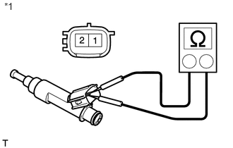
Check the resistance.
Measure the resistance according to the value(s) in the table below.
Standard Resistance
Tester Connection
Condition
Specified Condition
1 - 2
20°C (68°F)
11.6 to 12.4 Ω
Table 1. Text in Illustration *1
Component without harness connected
(Fuel Injector Assembly)
If the result is not as specified, replace the injector assembly.
Check the injection volume.
CAUTION:Perform the inspection in a well-ventilated area.
Do not perform the inspection near any naked flames.
-
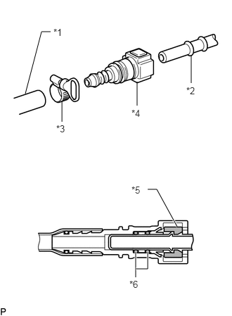
Connect SST (fuel tube connector) to SST (hose), and then connect them to the fuel pipe (vehicle side).
09268-31014
95336-08070
09268-41500
09268-41700
Table 2. Text in Illustration *1
SST (Hose)
*2
Fuel Pipe
*3
SST (Hose Band)
*4
SST (Fuel Tube Connector)
*5
Retainer
*6
O-Ring
Install the O-ring onto the fuel injector.
-
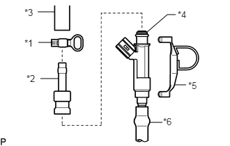
Connect SST (adapter and hose) to the injector, and hold the injector and union with SST (clamp).
09268-31014
95336-08070
09268-41110
09268-41300
09268-41700
Table 3. Text in Illustration *1
SST (Hose Band)
*2
SST (Adapter)
*3
SST (Hose)
*4
O-Ring
*5
SST (Clamp)
*6
Vinyl Tube
-
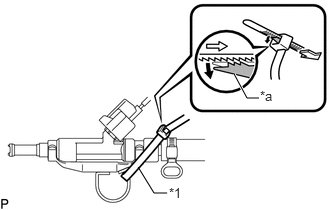
Pass SST (tie band) through the loop on the handle of SST (clamp) to secure SST (clamp) to SST (adapter).
09268-31014
09268-41800
Table 4. Text in Illustration *1
SST (Tie Band)
*a
Lock
Note:As SST (tie band) does not completely prevent SST (clamp) from becoming loose, do not subject the parts to any impacts while using them.
Before using SST (tie band), make sure that there is no deterioration, damage or cracks. If there are any abnormalities, replace SST.
Tip:When removing SST (tie band), disengage the lock.
Check that SST (clamp) and SST (adapter) cannot be easily separated.
Install a vinyl tube onto the injector.
CAUTION:Install a suitable vinyl tube onto the injector to prevent gasoline from splashing out.
Put the injector into a graduated cylinder.
Operate the fuel pump (Click here).
-
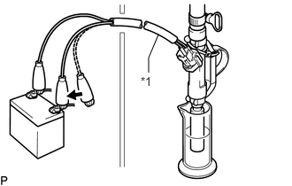
Connect SST (wire) to the injector and battery for 15 seconds, and measure the injection volume with the graduated cylinder. Test each injector 2 or 3 times.
09842-30080
Standard injection volume
60 to 73 cc (3.7 to 4.5 cu. in.) per 15 seconds
Difference between each injector
13 cc (0.8 cu. in.) or less
Table 5. Text in Illustration *1
SST (Wire)

Connect
Note:Make sure that SST (EFI inspection wire H) is securely connected.
Always do the switching at the battery side.
If the injection volume is not as specified, replace the injector assembly.
-
-
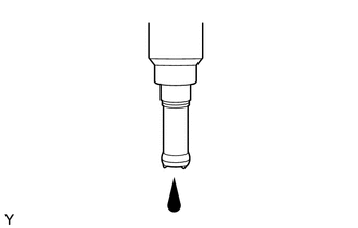
Inspect for fuel leak.
In the condition above, disconnect the test probes of SST (wire) from the battery and check the fuel leakage from the injector.
Fuel drop
1 drop or less every 12 minutes
-