FRONT BUMPER(except Sport Package) DISASSEMBLY
PROCEDURE
-
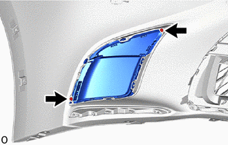
REMOVE HEADLIGHT WASHER COVER LH
-
REMOVE HEADLIGHT WASHER COVER RH
Tech Tips
Use the same procedure described for the LH side.
-
REMOVE HEADLIGHT WASHER ACTUATOR SUB-ASSEMBLY LH
-
REMOVE HEADLIGHT WASHER ACTUATOR SUB-ASSEMBLY RH
Tech Tips
Use the same procedure described for the LH side.
-
REMOVE NO. 2 WASHER BRACKET
-
REMOVE WASHER BRACKET
Tech Tips
Use the same procedure described for the No. 2 washer bracket.
-
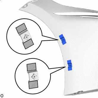
REMOVE NO. 1 HEADLIGHT CLEANER HOSE
-
Detach the clamp and remove the No. 1 headlight cleaner hose.
-
-
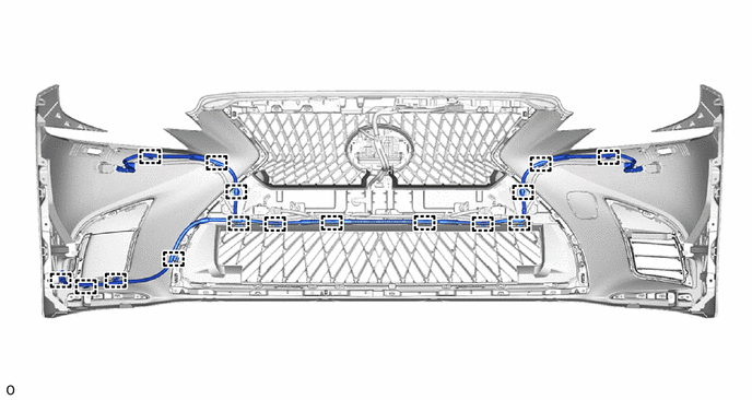
REMOVE NO. 4 ENGINE ROOM WIRE
-
Disconnect each connector.
Note
Do not apply excessive loads to the retainer. Otherwise, it may peel off.
-
Detach the clamp and remove the No. 4 engine room wire.
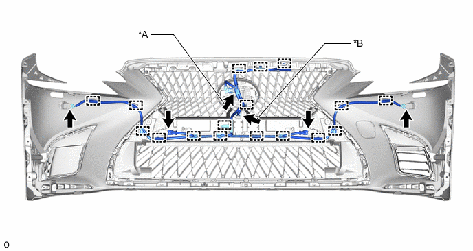
*A w/ Dynamic Radar Cruise Control System *B w/ Panoramic View Monitor System
-
-
REMOVE FRONT CORNER ULTRASONIC SENSOR
-
REMOVE FRONT CORNER ULTRASONIC SENSOR RETAINER
-
REMOVE FRONT CENTER ULTRASONIC SENSOR
-
REMOVE FRONT ULTRASONIC SENSOR CLIP
-
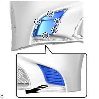
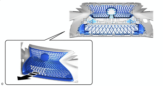
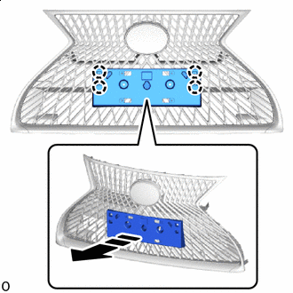
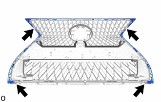
REMOVE RADIATOR GRILLE PROTECTOR
-
Detach the clip and double-sided tape and remove the radiator grille protector.
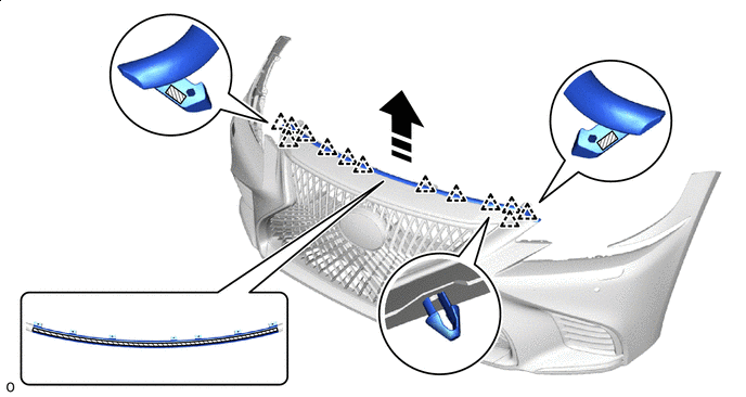

Remove in this Direction 
Double-sided Tape
-
-
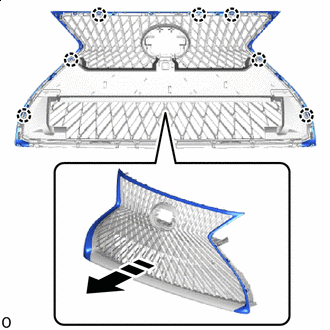
REMOVE UPPER RADIATOR GRILLE
-
Remove the 6 screws.
-
Remove the 4 clips.
-
Detach the guide and remove the upper radiator grille.
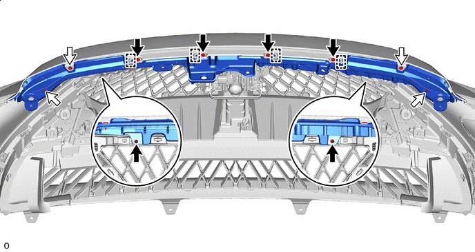

Screw 
Clip
-
-
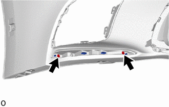
REMOVE FRONT BUMPER NO. 2 SIDE RETAINER LH
Tech Tips
When removing the front bumper No. 2 side retainer LH, heat the front bumper cover and front bumper No. 2 side retainer LH using a heat light.
Standard Item Temperature Front Bumper Cover 20 to 30°C (68 to 86°F) Front Bumper No. 2 Side Retainer LH 20 to 30°C (68 to 86°F) CAUTION:
-
Do not touch the heat light and heated parts.
-
Touching the heat light may result in burns.
-
Touching heated parts for a long time may result in burns.
*a Heated Part *b Heat Light
-
Double-sided Tape Remove the front bumper No. 2 side retainer LH.
-
-
REMOVE FRONT BUMPER NO. 2 SIDE RETAINER RH
Tech Tips
Use the same procedure described for the LH side.
-
REMOVE FRONT BUMPER REINFORCEMENT EXTENSION LH
-
Screw Clip Remove the 4 screws.
-
Remove the clip and front bumper reinforcement extension LH.
-
Remove the grommet from the front bumper reinforcement extension LH.
-
-
REMOVE FRONT BUMPER REINFORCEMENT EXTENSION RH
Tech Tips
Use the same procedure described for the LH side.
-
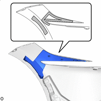
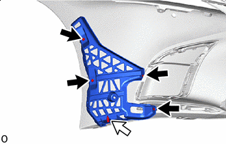
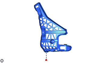
REMOVE RADIATOR GRILLE BRACKET LH
-
Remove the 2 screws.
-
Remove in this Direction Detach the claw and remove the radiator grille bracket LH as shown in the illustration.
-
-
REMOVE RADIATOR GRILLE BRACKET RH
Tech Tips
Use the same procedure described for the LH side.
-
REMOVE RADIATOR GRILLE SIDE MOULDING LH
-
Remove the 2 screws.
-
Remove in this Direction Detach the claw and guide and remove the radiator grille side moulding LH as shown in the illustration.
-
-
REMOVE RADIATOR GRILLE SIDE MOULDING RH
Tech Tips
Use the same procedure described for the LH side.
-
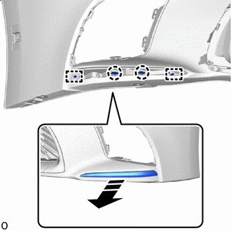
REMOVE FRONT BUMPER RETAINER
Tech Tips
-
When removing the front bumper retainer, heat the front bumper cover and front bumper retainer using a heat light.
-
Use the same procedure for the RH and LH side.
Standard Item Temperature Front Bumper Cover 20 to 30°C (68 to 86°F) Front Bumper Retainer 20 to 30°C (68 to 86°F) CAUTION:
-
Do not touch the heat light and heated parts.
-
Touching the heat light may result in burns.
-
Touching heated parts for a long time may result in burns.
*a Heated Part *b Heat Light
-
Double-sided Tape Remove the 2 front bumper retainers.
-
-
REMOVE FRONT BUMPER HOLE COVER RH
-
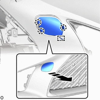
Remove in this Direction Detach the claw.
-
Detach the anti-drop hook and remove the front bumper hole cover RH as shown in the illustration.
-
-
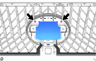
REMOVE FRONT TELEVISION CAMERA ASSEMBLY (w/ Panoramic View Monitor System)
-
REMOVE MILLIMETER WAVE RADAR SENSOR ASSEMBLY (w/ Dynamic Radar Cruise Control System)
-
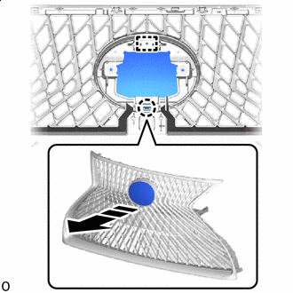
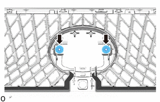
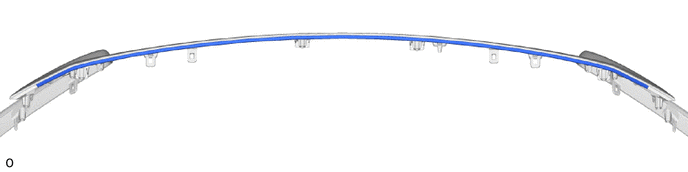
REMOVE RADIATOR GRILLE SEAL
Tech Tips
When removing the radiator grille seal, heat the radiator grille assembly and radiator grille seal using a heat light.
Standard Item Temperature Radiator Grille Assembly 20 to 30°C (68 to 86°F) Radiator Grille Seal 20 to 30°C (68 to 86°F) CAUTION:
-
Do not touch the heat light and heated parts.
-
Touching the heat light may result in burns.
-
Touching heated parts for a long time may result in burns.
*a Heated Part *b Heat Light
-
Remove the radiator grille seal.
-
-
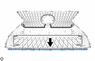
REMOVE RADIATOR GRILLE ASSEMBLY
-
Remove the 17 screws.
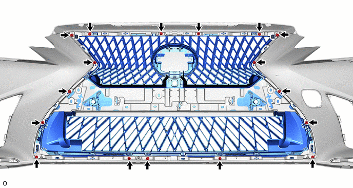
-
Detach the claw and guide and remove the radiator grille assembly as shown in the illustration.
Remove in this Direction - -
-
-
REMOVE FRONT BUMPER EXTENSION MOUNTING BRACKET
-
for Type A:
-
Remove the 2 screws.
-
Remove in this Direction Detach the claw and remove the front bumper extension mounting bracket.
-
-
for Type B:
-
Remove the 2 screws.
-
Remove in this Direction Detach the claw and remove the front bumper extension mounting bracket.
-
-
-
REMOVE RADIATOR GRILLE (OR FRONT PANEL) EMBLEM
-
Remove the 2 screws.
-
Remove in this Direction Detach the claw and guide and remove the radiator grille (or front panel) emblem as shown in the illustration.
-
-
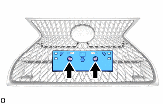
REMOVE NUT
-
Remove the 2 nuts.
-
-
REMOVE RADIATOR GRILLE MOULDING
-
Remove the 4 screws.
-
Remove in this Direction Detach the claw and remove the radiator grille moulding as shown in the illustration.
-
-
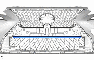
REMOVE UPPER RADIATOR SEAL
Tech Tips
When removing the upper radiator seal, heat the radiator grille moulding and upper radiator seal using a heat light.
Standard Item Temperature Radiator Grille Moulding 20 to 30°C (68 to 86°F) Upper Radiator Seal 20 to 30°C (68 to 86°F) CAUTION:
-
Do not touch the heat light and heated parts.
-
Touching the heat light may result in burns.
-
Touching heated parts for a long time may result in burns.
*a Heated Part *b Heat Light
-
Remove the upper radiator seal.
-
-
REMOVE LOWER RADIATOR GRILLE MOULDING
-
Remove the screw.
-
Remove in this Direction Detach the claw and remove the lower radiator grille moulding as shown in the illustration.
-
-
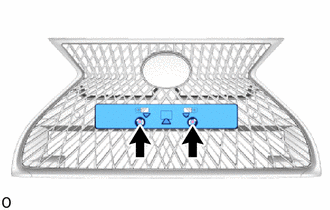
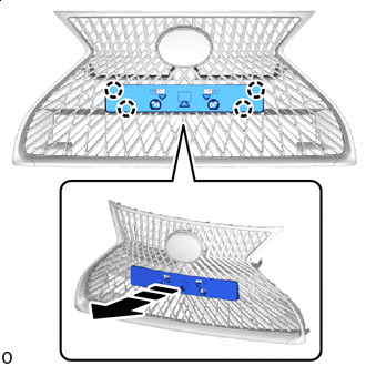
REMOVE NO. 1 MOULDING TAPE
Tech Tips
-
When removing the No. 1 moulding tape, heat the front bumper cover and No. 1 moulding tape using a heat light.
-
Use the same procedure for the RH and LH side.
Standard Item Temperature Front Bumper Cover 20 to 30°C (68 to 86°F) No. 1 Moulding Tape 20 to 30°C (68 to 86°F) CAUTION:
-
Do not touch the heat light and heated parts.
-
Touching the heat light may result in burns.
-
Touching heated parts for a long time may result in burns.
*a Heated Part *b Heat Light
-
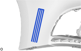
Remove the No. 1 moulding tape.
-
-
REMOVE FRONT BUMPER ENERGY ABSORBER SUB-ASSEMBLY
-
Check that the engine switch off.
-
Check that the cable is disconnected from the negative (-) battery terminal.
CAUTION:
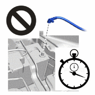
Wait at least 90 seconds after disconnecting the cable from the negative (-) battery terminal to disable the SRS system.
-
Disconnect the 2 connectors of the pedestrian detection chamber assembly.
Note
When disconnecting any pedestrian detection chamber assembly connector, take care not to damage the pedestrian detection chamber assembly wire harness.
-
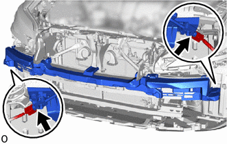
Push down the housing lock and slide the CPA. (At this time, the connector cannot be disconnected yet.)
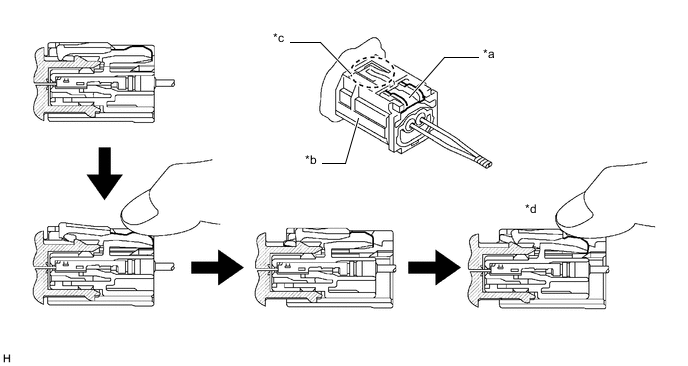
*a Housing Lock *b CPA *c CPA Upper Part *d Connector Lock is Released -
Push the housing lock again and disconnect the connector.
Note
Do not push down the upper part of the CPA shown in the illustration when disconnecting the pedestrian detection chamber assembly connector.
-
After disconnecting the connector, check that the position of the housing lock is correct as shown in the illustration.
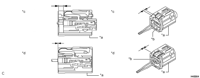
*a CPA *b Housing *c Correct *d Incorrect
-
-
Remove the 2 bolts.
-
Detach the claw and guide and remove the front bumper absorber sub-assembly as shown in the illustration.
-
-
REMOVE FRONT BUMPER NO. 2 ENERGY ABSORBER
-
Remove the bolt and front bumper No. 2 energy absorber.
-
-
REMOVE LOWER ARM BRACKET BRACE SUB-ASSEMBLY LH
-
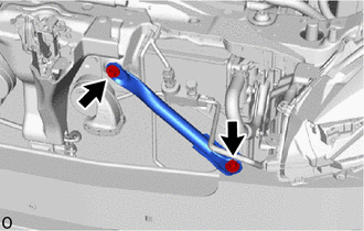
Remove the 2 bolts and lower arm bracket brace sub-assembly LH.
-
-
REMOVE LOWER ARM BRACKET BRACE SUB-ASSEMBLY RH
Tech Tips
Use the same procedure described for the LH side.
-
REMOVE FRONT BUMPER SIDE RETAINER LH
-
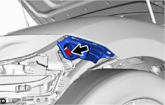
Remove the bolt.
-
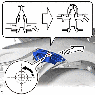
*a 90° Rotation Direction 
Remove in this Direction Using a screwdriver, turn the clip 90° and detach the clip and remove the front bumper side retainer LH as shown in the illustration.
-
-
REMOVE FRONT BUMPER SIDE RETAINER RH
Tech Tips
Use the same procedure described for the LH side.
-
REMOVE HEADLIGHT ASSEMBLY LH
-
REMOVE HEADLIGHT ASSEMBLY RH
Tech Tips
Use the same procedure described for the LH side.
-
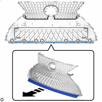
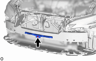
REMOVE FRONT BUMPER REINFORCEMENT SUB-ASSEMBLY
-
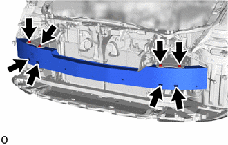
Remove the 8 bolts.
-
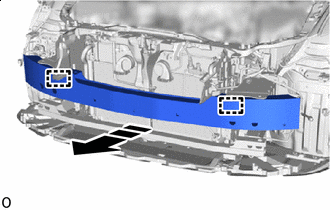
Remove in this Direction Detach the guide and remove the front bumper reinforcement sub-assembly as shown in the illustration.
-
-
REMOVE FRONT BUMPER NO. 2 REINFORCEMENT SUB-ASSEMBLY
-
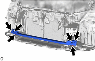
Remove the 6 nuts and front bumper No. 2 reinforcement sub-assembly.
-