POWER WINDOW CONTROL SYSTEM Auto Up / Down Function does not Operate
DESCRIPTION
If the auto up/down function does not operate, the cause may be one or more of the following:
-
The recorded power window fully closed position, which is stored in the power window regulator master switch assembly, was erased as a result of: 1) the PWR H-fuse or DOOR fuse being replaced; or 2) the battery cable and the master switch's connector being disconnected.
-
The power window regulator master switch assembly has a malfunction.
-
The pulse sensors in the front power window regulator motor assembly (for driver side)*1 or front door window regulator sub-assembly*2 have a malfunction.
-
The wiring between the power window regulator master switch assembly and the front power window regulator motor assembly (for driver side)*1 or front door window regulator sub-assembly*2 is open or short-circuited.
-
*1: w/o Regulator
-
*2: w/ Regulator
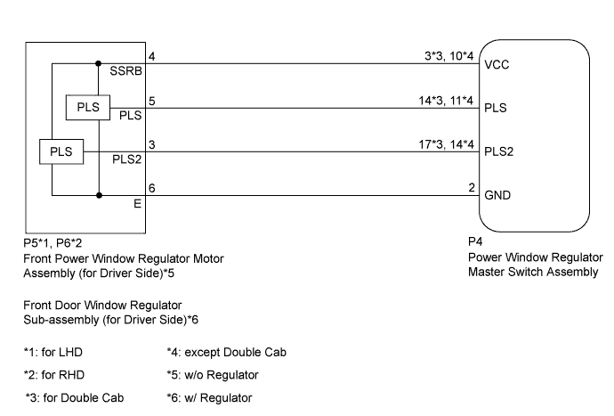
WIRING DIAGRAM
INSPECTION PROCEDURE
PROCEDURE
-
CHECK MANUAL UP/DOWN FUNCTION (FOR DRIVER SIDE)
-
Check that the manual up/down function operates normally.
OK Manual up/down function operates normally.
NG 
GO TO DRIVER SIDE POWER WINDOW MANUAL FUNCTION DOES NOT OPERATE WITH POWER WINDOW MASTER SWITCH Click here
OK 
-
-
CHECK LIGHT OF POWER WINDOW REGULATOR MASTER SWITCH ASSEMBLY
-
Turn the ignition switch ON.
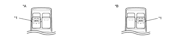
Text in Illustration *A for LHD *B for RHD *1 AUTO Light - - -
Operate the master switch's driver side power window switch for 2 seconds or more.
-
Check the blinking pattern of the AUTO light. Compare the blinking pattern with the illustration.
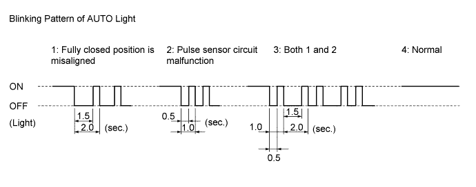
Result Blinking Pattern Proceed to 1 or 3 A 2 B 4 C
B 
CHECK HARNESS AND CONNECTOR (POWER WINDOW REGULATOR MASTER SWITCH - FRONT POWER WINDOW REGULATOR MOTOR [FOR DRIVER SIDE] OR FRONT DOOR WINDOW REGULATOR [FOR DRIVER SIDE]) Click here
C
REPLACE POWER WINDOW REGULATOR MASTER SWITCH ASSEMBLY
A
-
-
RESET FRONT POWER WINDOW REGULATOR MOTOR ASSEMBLY (FOR DRIVER SIDE) OR FRONT DOOR WINDOW REGULATOR SUB-ASSEMBLY (FOR DRIVER SIDE)
-
Check that the power window operates normally after reset Click here.
OK Power window operates normally.
NG
CHECK HARNESS AND CONNECTOR (POWER WINDOW REGULATOR MASTER SWITCH - FRONT POWER WINDOW REGULATOR MOTOR [FOR DRIVER SIDE] OR FRONT DOOR WINDOW REGULATOR [FOR DRIVER SIDE]) Click here
OK 
END
-
-
CHECK HARNESS AND CONNECTOR (POWER WINDOW REGULATOR MASTER SWITCH - FRONT POWER WINDOW REGULATOR MOTOR [FOR DRIVER SIDE] OR FRONT DOOR WINDOW REGULATOR [FOR DRIVER SIDE])
-
*1: for LHD
-
*2: for RHD
-
*3: for Double Cab
-
*4: except Double Cab
-
Disconnect the P4 power window regulator master switch assembly connector.
-
w/o Regulator:
-
Disconnect the P5*1 or P6*2 front power window regulator motor assembly (for driver side) connector.
-
-
w/ Regulator:
-
Disconnect the P5*1 or P6*2 front door window regulator sub-assembly (for driver side) connector.
-
-
Measure the resistance according to the value(s) in the table below.
Standard Resistance for LHD Tester Connection Condition Specified Condition P4-3 (VCC) - P5-4 (SSRB)*3
P4-10 (VCC) - P5-4 (SSRB)*4
Always Below 1 Ω P4-14 (PLS) - P5-5 (PLS)*3
P4-11 (PLS) - P5-5 (PLS)*4
Always Below 1 Ω P4-17 (PLS2) - P5-3 (PLS2)*3
P4-14 (PLS2) - P5-3 (PLS2)*4
Always Below 1 Ω P4-2 (GND) - P5-6 (E) Always Below 1 Ω P4-3 (VCC) or P5-4 (SSRB) - Body ground*3
P4-10 (VCC) or P5-4 (SSRB) - Body ground*4
Always 10 kΩ or higher P4-14 (PLS) or P5-5 (PLS) - Body ground*3
P4-11 (PLS) or P5-5 (PLS) - Body ground*4
Always 10 kΩ or higher P4-17 (PLS2) or P5-3 (PLS2) - Body ground*3
P4-14 (PLS2) or P5-3 (PLS2) - Body ground*4
Always 10 kΩ or higher for RHD Tester Connection Condition Specified Condition P4-3 (VCC) - P6-4 (SSRB)*3
P4-10 (VCC) - P6-4 (SSRB)*4
Always Below 1 Ω P4-14 (PLS) - P6-5 (PLS)*3
P4-11 (PLS) - P6-5 (PLS)*4
Always Below 1 Ω P4-17 (PLS2) - P6-3 (PLS2)*3
P4-14 (PLS2) - P6-3 (PLS2)*4
Always Below 1 Ω P4-2 (GND) - P6-6 (E) Always Below 1 Ω P4-3 (VCC) or P6-4 (SSRB) - Body ground*3
P4-10 (VCC) or P6-4 (SSRB) - Body ground*4
Always 10 kΩ or higher P4-14 (PLS) or P6-5 (PLS) - Body ground*3
P4-11 (PLS) or P6-5 (PLS) - Body ground*4
Always 10 kΩ or higher P4-17 (PLS2) or P6-3 (PLS2) - Body ground*3
P4-14 (PLS2) or P6-3 (PLS2) - Body ground*4
Always 10 kΩ or higher
NG
REPAIR OR REPLACE HARNESS OR CONNECTOR
OK
-
-
CHECK POWER WINDOW REGULATOR MASTER SWITCH ASSEMBLY (PLS, PLS2 SIGNAL)
-
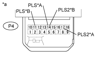
Text in Illustration *A for Double Cab *B except Double Cab *a Component with harness connected
(Power Window Regulator Master Switch Assembly)
Remove the power window regulator master switch assembly with its connectors still connected.
-
Using an oscilloscope, check the waveform.
OK for Double Cab Tester Connection Switch Condition Specified Condition P4-14 (PLS) - Body ground Ignition switch ON, driver side power window switch off → up or down Pulse waveform is output P4-17 (PLS2) - Body ground Ignition switch ON, driver side power window switch off → up or down Pulse waveform is output except Double Cab Tester Connection Switch Condition Specified Condition P4-11 (PLS) - Body ground Ignition switch ON, driver side power window switch off → up or down Pulse waveform is output P4-14 (PLS2) - Body ground Ignition switch ON, driver side power window switch off → up or down Pulse waveform is output Result Result Proceed to NG A OK (w/o Regulator) B OK (w/ Regulator) C
B
REPLACE FRONT POWER WINDOW REGULATOR MOTOR ASSEMBLY (FOR DRIVER SIDE)
C
REPLACE FRONT DOOR WINDOW REGULATOR SUB-ASSEMBLY (FOR DRIVER SIDE)
A
REPLACE POWER WINDOW REGULATOR MASTER SWITCH ASSEMBLY
-