ENTRY AND START SYSTEM(for Start Function) Engine does not Start
| DTC Code | DTC Name |
|---|---|
| Engine does not Start |
DESCRIPTION
When the key is in the vehicle and the engine switch is pressed, the power management control ECU receives a signal and changes the power source mode. In addition, when the shift lever is in P or N and the brake pedal is depressed, the engine can be started by pressing the engine switch.
When the power management control ECU is replaced with a new one and the cable is connected to the negative (-) battery terminal, the power source mode changes to on (IG).
When the battery cable is disconnected and reconnected, the power source returns to the mode it was in before the battery cable was disconnected.
WIRING DIAGRAM
Refer to "System Diagram" (Click here)
CAUTION / NOTICE / HINT
When using the intelligent tester with the engine switch off, perform either of the following: 1) Turn a courtesy light switch on and off at intervals of 1.5 seconds or less until communication between the intelligent tester and vehicle begins, or 2) connect the intelligent tester to the vehicle and select "MANUAL" from the initial screen on the intelligent tester, and then select "KEY REGIST" under Model Code.
The entry and start system uses multiplex communication. First perform the inspections in "How to Proceed with Troubleshooting" to confirm that there are no communication malfunctions before proceeding with troubleshooting (Click here).
If the entry and start system is disabled through the customize function, enable the system before performing troubleshooting (Click here).
Inspect the fuses of circuits related to this system before performing the following inspection procedure.
Before replacing the steering lock actuator assembly (steering lock ECU), certification ECU or ID code box, refer to the Service Bulletin.
If the steering lock actuator assembly (steering lock ECU) is replaced, be sure to confirm that the steering is unlocked by turning the steering wheel to the left and right before starting the engine. If the steering is locked for any reason, open and close a door with the engine switch off, and then unlock the steering by pressing the engine switch. This prevents the engine from starting while the steering is locked.
After completing repairs, confirm that the problem does not occur.
Problem Symptom |
Data List Item |
Active Test Item |
|---|---|---|
Engine does not start |
|
- |
If the brake pedal is repeatedly depressed while the engine is stopped, the brake booster pressure is released and the force required to depress the brake pedal to illuminate the stop lights increases.
PROCEDURE
CHECK BATTERY
Measure the battery voltage.
Standard voltage
11 to 14 V
Tip:A simple method to determine whether the battery is depleted is to operate the horn.
Result
Result
OK
NG
NG GO TO CHARGING SYSTEM
READ VALUE USING INTELLIGENT TESTER (POWER SUPPLY OPEN) AND CHECK FOR DTC
Read the value using the intelligent tester (Power Supply Open).
Connect the intelligent tester to the DLC3.
Turn the engine switch on (IG).
Turn the intelligent tester on.
Enter the following menus: Body / Entry&Start / Data List.
According to the display on the intelligent tester, read the Data List.
Body Electrical > Entry&Start > Data List
Tester Display
Measurement Item
Range
Normal Condition
Diagnostic Note
Power Supply Open
Record of malfunction of signal sent to steering lock actuator assembly (motor) from power management control ECU (open circuit) (DTC B2782 stored)
NG (PAST) or OK
OK: No record of malfunction (open circuit)
NG (PAST): Record of malfunction (open circuit) exists
This item records malfunctions in the circuit between the power management control ECU and steering lock actuator assembly (motor).
Using the intelligent tester, confirm the output of DTCs for all systems.
Result
Result
Proceed to
No DTC is output and power supply open has not occurred in past
A
DTCs are output (except DTC B2782)
B
Power supply open has occurred in past and/or DTC B2782 is output
C
CHECK ENGINE SWITCH CONDITION
When the key is inside the vehicle and the shift lever is in P, push the engine with the brake pedal released switch and check that the power source mode changes.
Result
Result
Proceed to
Power source mode changes as follows (normal): off → on (ACC) → on (IG) → off
A
Power source mode does not change to on (IG) or on (ACC)
B
Power source mode does not change to on (IG) but does change to on (ACC)
C
Power source mode does not change to on (ACC) but does change to on (IG)
D
CHECK CRANKING FUNCTION
Get into the vehicle while carrying the key.
Move the shift lever to P.
Depress the brake pedal.
Confirm that the engine switch indicator illuminates in green, and then press the engine switch and check that the engine cranks.
Result
Result
Proceed to
Engine does not crank
A
Engine cranks, but there is not initial combustion
B
Engine cranks, but is difficult to start
C
CHECK SECURITY INDICATOR LIGHT (ENGINE IMMOBILISER SYSTEM UNSET)
Get into the vehicle while carrying the key, move the shift lever to P, press the engine switch while not depressing the brake pedal and check that the security indicator light stops blinking and turns off at the same time the power source mode changes to on (ACC).
OK
The security indicator light stops blinking and turns off at the same time the power source mode changes to on (ACC).
Tip:If the security indicator light stops blinking and turns off at the same time the power source mode changes to on (ACC), the engine immobiliser function can be presumed to be normal.
Result
Result
OK
NG
NG READ VALUE USING INTELLIGENT TESTER (S CODE CHECK)Click here
CHECK ENGINE SWITCH INDICATOR LIGHT
Get into the vehicle while carrying the key, move the shift lever to P, press the engine switch while depressing the brake pedal and check that the engine switch indicator changes.
OK
The indicator illuminates in green.
Tip:If the engine switch indicator illuminates in green when the procedure above is performed, the P, N and brake signals can be considered to be normal.
Result
Result
OK
NG
NG READ VALUE USING INTELLIGENT TESTER (SHIFT P SIGNAL, NEUTRAL SW/ CLUTCH SW, SHIFT POSITION P OR N)Click here
READ VALUE USING INTELLIGENT TESTER (STARTER SW)
Connect the intelligent tester to the DLC3.
Turn the engine switch on (IG).
Turn the intelligent tester on.
Enter the following menus: Body / Starting Control / Data List.
Get into the vehicle while carrying the key, move the shift lever to P, press the engine switch while depressing the brake pedal and confirm that the Data List item changes.
Body Electrical > Starting Control > Data List
Tester Display
Measurement Item
Range
Normal Condition
Diagnostic Note
Starter SW
Starter activation request
ON or OFF
ON: Starter activation requested
OFF: Starter activation not requested
When there is a malfunction, the engine cannot be cranked.
OK
The Data List item changes.
Result
Result
OK
NG
INSPECT ST RELAY
-
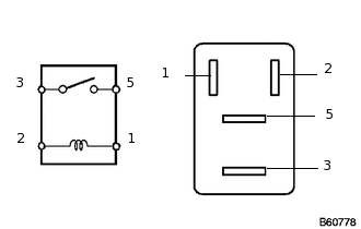
Remove the ST relay from the engine room relay block.
Measure the resistance according to the value(s) in the table below.
Standard Resistance
Tester Connection
Condition
Specified Condition
1 - 2
20°C (68°F)
93.8 to 136.4 Ω
3 - 5
Battery voltage notapplied to terminals 1and 2
10 kΩ or higher
Battery voltage appliedto terminals 1 and 2
Below 1 Ω
Reinstall the ST relay to the engine room relay block.
Result
Result
OK
NG
NG REPLACE ST RELAY
-
CHECK HARNESS AND CONNECTOR (POWER MANAGEMENT CONTROL ECU - BODY GROUND)
-
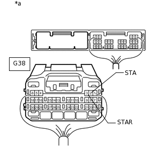
*a
Rear view of wire harness connector
(to Power Management Control ECU)
Disconnect the G38 power management control ECUconnector.
Move the shift lever to P or N.
Measure the resistance according to the value(s) in the table below.
Standard Resistance
Tester Connection
Condition
Specified Condition
G38-3 (STAR) - Bodyground
20°C (68°F)
93.8 to 136.4 Ω
G38-2 (STA) - Bodyground
Result
Result
OK
NG
NG REPAIR OR REPLACE HARNESS OR CONNECTOR
-
INSPECT STARTER ASSEMBLY
Inspect the starter assembly.
Result
Result
OK
NG
CHECK HARNESS AND CONNECTOR (BATTERY - STARTER AND ENGINE ROOM RELAY BLOCK)
Remove the starter assembly from the vehicle to perform an inspection.
Remove the ST relay from the engine room relay block.
Measure the voltage according to the value(s) in the table below.
Standard Voltage
Tester Connection
Condition
Specified Condition
D2-1 - Body ground
Always
11 to 14 V
5 - Body ground
Always
11 to 14 V
Measure the resistance according to the value(s) in the table below.
Standard Resistance
Tester Connection
Condition
Specified Condition
3 - D3-1
Always
Below 1 Ω
3 or D3-1 - Body ground
Always
10 kΩ or higher
Result
Result
OK
NG
NG REPAIR OR REPLACE HARNESS OR CONNECTOR
READ VALUE USING INTELLIGENT TESTER (SHIFT P SIGNAL, NEUTRAL SW/ CLUTCH SW, SHIFT POSITION P OR N)
Connect the intelligent tester to the DLC3.
Turn the engine switch on (IG).
Turn the intelligent tester on.
Enter the following menus: Body / Power Source Control or Starting Control / Data List.
According to the display on the intelligent tester, read the Data List.
Body Electrical > Power Source Control > Data List
Tester Display
Measurement Item
Range
Normal Condition
Diagnostic Note
Shift P Signal
Shift position (P)
ON or OFF
ON: Shift lever in P
OFF: Shift lever not in P
Use this item to determine if the shift position switch is malfunctioning.
Neutral SW/ Clutch SW
Shift position (P, N) (for Automatic Transmission) or state of clutch pedal (for Manual Transmission)
ON or OFF
ON: Shift lever in P or N (for Automatic Transmission) or clutch pedal depressed (for Manual Transmission)
OFF: Shift lever not in P or N (for Automatic Transmission) or clutch pedal released (for Manual Transmission)
Use this item to help determine if the park/neutral position switch (for Automatic Transmission) or clutch switch (for Manual Transmission) is malfunctioning.
The engine cannot be started when this item is "OFF".
Body Electrical > Starting Control > Data List
Tester Display
Measurement Item
Range
Normal Condition
Diagnostic Note
Shift Position P or N
Condition of park/neutral position switch
ON or OFF
ON: Shift lever in P or N
OFF: Shift lever not in P or N
When there is a malfunction, the engine cannot be cranked.
OK
The item in the Data List changes according to the shift position.
Result
Result
OK
NG
NG INSPECT PARK/NEUTRAL POSITION SWITCHClick here
READ VALUE USING INTELLIGENT TESTER (STOP LIGHT SWITCH1)
Connect the intelligent tester to the DLC3.
Turn the engine switch on (IG).
Turn the intelligent tester on.
Enter the following menus: Body / Power Source Control / Data List.
According to the display on the intelligent tester, read the Data List.
Body Electrical > Power Source Control > Data List
Tester Display
Measurement Item
Range
Normal Condition
Diagnostic Note
Stop Light Switch1
Stop light switch 1
ON or OFF
ON: Brake pedal depressed
OFF: Brake pedal released
-
OK
The item in the Data List changes when the brake pedal is depressed and released.
Result
Result
OK
NG
INSPECT STOP LIGHT SWITCH ASSEMBLY
Disconnect the A5 stop light switch connector.
Inspect the stop light switch assembly.
Result
Result
OK
NG
CHECK HARNESS AND CONNECTOR (POWER MANAGEMENT CONTROL ECU - STOP LIGHT SWITCH ASSEMBLY)
Disconnect the G38 power management control ECU connector.
Disconnect the A5 stop light switch assembly connector.
Measure the resistance according to the value(s) in the table below.
Standard Resistance
Tester Connection
Condition
Specified Condition
G38-11 (STP1) - A5-1
Always
Below 1 Ω
G38-11 (STP1) or A5-1 - Body ground
Always
10 kΩ or higher
-
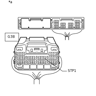
*a
Rear view of wire harness connector
(to Power Management Control ECU)
Reconnect the A5 stop light switch assembly connector.
Measure the voltage according to the value(s) in the table below.
Standard Voltage
Tester Connection
Condition
Specified Condition
G38-11 (STP1) - Body ground
Brake pedal not depressed
Below 1 V
Brake pedal depressed
([Voltage at terminal AM21 or AM22] minus 2.0 V) or higher
Result
Result
OK
NG
NG REPAIR OR REPLACE HARNESS OR CONNECTOR
INSPECT PARK/NEUTRAL POSITION SWITCH
Disconnect the C33 park/neutral position switch connector.
-
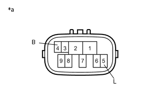
*a
Component without harness connected
(Park/Neutral Position Switch)
Measure the resistance according to the value(s) in the table below.
Standard Resistance
Tester Connection
Condition
Specified Condition
4 (B) - 5 (L)
Shift lever in P or N
Below 1 Ω
Shift lever not in P or N
10 kΩ or higher
Result
Result
OK
NG
CHECK HARNESS AND CONNECTOR (POWER MANAGEMENT CONTROL ECU - PARK/NEUTRAL POSITION SWITCH)
Disconnect the G38 power management control ECU connector.
Disconnect the C33 park/neutral position switch connector.
Measure the resistance according to the value(s) in the table below.
Standard Resistance
Tester Connection
Condition
Specified Condition
G38-3 (STAR) - C33-4 (B)
Always
Below 1 Ω
G38-3 (STAR) - Body ground
Always
10 kΩ or higher
Reconnect the park/neutral position switch connector.
Measure the voltage according to the value(s) in the table below.
Standard Voltage
Tester Connection
Condition
Specified Condition
G38-3 (STAR) - Body ground
Engine switch pressed and held with brake pedal depressed (starter on) → Engine switch released after approximately 1 second elapses (starter off)
6 V or more* → 1.8 V or less
Tip:*: When the engine is cranking, the battery voltage may momentarily drop to approximately 6 V.
Result
Result
OK
NG
NG REPAIR OR REPLACE HARNESS OR CONNECTOR
READ VALUE USING INTELLIGENT TESTER (S CODE CHECK)
Connect the intelligent tester to the DLC3.
Turn the engine switch on (IG).
Turn the intelligent tester on.
Enter the following menus: Body Electrical / Entry&Start / Data List.
According to the display on the intelligent tester, read the Data List.
Body Electrical > Entry&Start > Data List
Tester Display
Measurement Item
Range
Normal Condition
Diagnostic Note
S Code Check
Verification result between certification ECU and ID code box
NG or OK
OK: Verification result normal
NG: Verification result abnormal
When a malfunction is present:
The ID code for the certification ECU or ID code box is not registered or the certification ECU or ID code box is malfunctioning.
The steering cannot be locked.
The steering cannot be unlocked (the engine cannot be started).
OK
OK (S code certification result normal) appears on the screen.
Result
Result
OK
NG
NG REPLACE CERTIFICATION ECUClick here
CHECK STEERING LOCK
Check that the steering unlocks when the engine switch is turned on (ACC).
OK
The steering unlocks.
Result
Result
OK
NG
NG READ VALUE USING INTELLIGENT TESTER (STEERING UNLOCK SWITCH)Click here
READ VALUE USING INTELLIGENT TESTER (IMMOBILISER)
Connect the intelligent tester to the DLC3.
Turn the engine switch on (IG).
Turn the intelligent tester on.
Enter the following menus: Body / Entry&Start / Data List.
According to the display on the intelligent tester, read the Data List.
Body Electrical > Entry&Start > Data List
Tester Display
Measurement Item
Range
Normal Condition
Diagnostic Note
Immobiliser
State of immobiliser system determined by certification ECU
Set or Unset
Unset: Engine immobiliser unset (engine switch on [ACC] or on [IG])
Set: Engine immobiliser set (engine switch off)
When the immobiliser cannot be unset, this item can be used to determine whether the certification ECU or ID code box is part of the problem.
The engine cannot be started when this item displays "Set".
HINT
The state of the immobiliser (whether it is set or unset) can be determined through the certification ECU. If this item displays "Set", the communication between the certification ECU and ID code box can be determined to be normal.
The security indicator light operation is only linked with the state of the immobiliser (set/unset), and is not related to the steering lock operation (lock/unlock), when the immobiliser is set, the security indicator light blinks.
OK
The Data List item changes to "unset" when the engine switch is turned on (ACC) or on (IG).
Result
Result
OK
NG
NG REPLACE CERTIFICATION ECUClick here
READ VALUE USING INTELLIGENT TESTER (STARTER REQUEST SIGNAL)
Connect the intelligent tester to the DLC3.
Turn the engine switch on (IG).
Turn the intelligent tester on.
Enter the following menus: Body / Power Source Control / Data List.
According to the display on the intelligent tester, read the Data List.
Body Electrical > Power Source Control > Data List
Tester Display
Measurement Item
Range
Normal Condition
Diagnostic Note
Starter Request Signal
Condition of engine start command signal
ON or OFF
ON: Engine switch pressed and held while carrying key with shift lever in P and brake pedal depressed
OFF: Engine switch released after approximately 1 second elapses
This item displays "ON" when cranking the engine.
The engine cannot be started when this item is "OFF".
OK
The display changes in response to the operation of the engine switch.
Note:Make sure that the engine switch indicator is illuminated in green before pressing the engine switch.
Result
Result
OK
NG
NG REPLACE CERTIFICATION ECU
REPLACE ID CODE BOX
Replace the ID code box with a new one.
Perform the registration procedure (Refer to Service Bulletin for registration).
Get into the vehicle while carrying the key, move the shift lever to P, press the engine switch while not depressing the brake pedal and check that the security indicator light stops blinking and turns off at the same time the power source mode changes to on (ACC).
Result
Result
NEXT
NEXT END
REPLACE CERTIFICATION ECU
Replace the certification ECU with a new one.
Perform the registration procedure (Refer to Service Bulletin for registration).
Use the Data List to check if S code certification is functioning properly again.
Body Electrical > Entry&Start > Data List
Tester Display
Measurement Item
Range
Normal Condition
Diagnostic Note
S Code Check
Verification result between certification ECU and ID code box
NG or OK
OK: Verification result normal
NG: Verification result abnormal
When a malfunction is present:
The ID code for the certification ECU or ID code box is not registered or the certification ECU or ID code box is malfunctioning.
The steering cannot be locked.
The steering cannot be unlocked (the engine cannot be started).
OK
OK (S code certification result normal) appears on the screen.
Result
Result
OK
NG
OK END
REPLACE ID CODE BOX
Replace the ID code box with a new one.
Perform the registration procedure (Refer to Service Bulletin for registration).
Use the Data List to check if S code certification is functioning properly again.
Body Electrical > Entry&Start > Data List
Tester Display
Measurement Item
Range
Normal Condition
Diagnostic Note
S Code Check
Verification result between certification ECU and ID code box
NG or OK
OK: Verification result normal
NG: Verification result abnormal
When a malfunction is present:
The ID code for the certification ECU or ID code box is not registered or the certification ECU or ID code box is malfunctioning.
The steering cannot be locked.
The steering cannot be unlocked (the engine cannot be started).
Result
Result
NEXT
NEXT END
READ VALUE USING INTELLIGENT TESTER (STEERING UNLOCK SWITCH)
Connect the intelligent tester to the DLC3.
Turn the engine switch on (IG).
Turn the intelligent tester on.
Enter the following menus: Body / Power Source Control / Data List.
According to the display on the intelligent tester, read the Data List.
Body Electrical > Power Source Control > Data List
Tester Display
Measurement Item
Range
Normal Condition
Diagnostic Note
Steering Unlock Switch
State of steering unlock sensor signal output from steering lock actuator assembly
ON or OFF
ON: Steering unlocked
OFF: Steering locked
When the shift lever is in P and the engine switch is off, if any door is opened or closed, the steering is locked.
When the key is inside the vehicle and the engine switch is turned on (ACC) or on (IG), the steering unlocks.
The engine cannot be started when the steering unlock signal is off.
OK
The item in the Data List indicates "OFF" (the steering is locked).
Result
Result
OK
NG
READ VALUE USING INTELLIGENT TESTER (L CODE CHECK)
Connect the intelligent tester to the DLC3.
Turn the engine switch on (IG).
Turn the intelligent tester on.
Enter the following menus: Body / Entry&Start / Data List.
According to the display on the intelligent tester, read the Data List.
Body Electrical > Entry&Start > Data List
Tester Display
Measurement Item
Range
Normal Condition
Diagnostic Note
L Code Check
Verification result between ID code box and steering lock actuator assembly
NG or OK
OK: Verification result normal
NG: Verification result abnormal
When a malfunction is present:
The ID code for the ID code box or steering lock actuator assembly is not registered or the ID code box or steering lock actuator is malfunctioning.
The steering cannot be locked.
The steering cannot be unlocked (the engine cannot be started).
OK
The Data List item changes to "OK" when the key is inside the vehicle.
Tip:Reasons for verification failure:
The steering lock ECU or ID code box is malfunctioning.
There is a problem with the communication between ECUs.
An ECU is replaced, but is not registered.
An ECU is replaced with an ECU which has a code already stored in it.
Result
Result
OK
NG
NG REPLACE STEERING LOCK ACTUATOR ASSEMBLY (STEERING LOCK ECU)Click here
REPLACE STEERING LOCK ACTUATOR ASSEMBLY (STEERING LOCK ECU)
Replace the steering lock actuator assembly (steering lock ECU) with a new one.
Perform the registration procedure (Refer to Service Bulletin for registration).
Turn the engine switch on (IG).
Operate the steering wheel and check the steering condition.
Result
Result
NEXT
NEXT END
REPLACE CERTIFICATION ECU
Replace the certification ECU with a new one.
Perform the registration procedures (Refer to Service Bulletin for registration).
Use the Data List to check if S code certification is functioning properly again.
Body Electrical > Entry&Start > Data List
Tester Display
Measurement Item
Range
Normal Condition
Diagnostic Note
S Code Check
Verification result between certification ECU and ID code box
Verification result between certification ECU and ID code box
OK: Verification result normal
NG: Verification result abnormal
When a malfunction is present:
The ID code for the certification ECU or ID code box is not registered or the certification ECU or ID code box is malfunctioning.
The steering cannot be locked.
The steering cannot be unlocked (the engine cannot be started).
OK
OK is displayed on the intelligent tester.
Result
Result
OK
NG
OK END
NG REPLACE ID CODE BOXClick here
REPLACE STEERING LOCK ACTUATOR ASSEMBLY (STEERING LOCK ECU)
Replace the steering lock actuator assembly (steering lock ECU) with a new one.
Perform the registration procedure (Refer to Service Bulletin for registration).
Use the Data List to check if L code certification is functioning properly again.
Body Electrical > Entry&Start > Data List
Tester Display
Measurement Item
Range
Normal Condition
Diagnostic Note
L Code Check
Verification result between ID code box and steering lock actuator assembly
NG or OK
OK: Verification result normal
NG: Verification result abnormal
When a malfunction is present:
The ID code for the ID code box or steering lock actuator assembly is not registered or the ID code box or steering lock actuator is malfunctioning.
The steering cannot be locked.
The steering cannot be unlocked (the engine cannot be started).
OK
OK (L code certification result normal) appears on the screen.
Result
Result
OK
NG
OK END
NG REPLACE ID CODE BOX
REPLACE ID CODE BOX
Replace the ID code box with a new one.
Perform the registration procedure (Refer to Service Bulletin for registration).
Use the Data List to check if S code certification is functioning properly again.
Body Electrical > Entry&Start > Data List
Tester Display
Measurement Item
Range
Normal Condition
Diagnostic Note
S Code Check
Verification result between certification ECU and ID code box
NG or OK
OK: Verification result normal
NG: Verification result abnormal
When a malfunction is present:
The ID code for the certification ECU or ID code box is not registered or the certification ECU or ID code box is malfunctioning.
The steering cannot be locked.
The steering cannot be unlocked (the engine cannot be started).
Result
Result
NEXT
NEXT END