HYDRAULIC BRAKE BOOSTER INSTALLATION
PROCEDURE
INSTALL BRAKE BOOSTER GASKET
Install a new brake booster gasket to the hydraulic brake booster.
INSTALL HYDRAULIC BRAKE BOOSTER ASSEMBLY
Install the hydraulic brake booster assembly with the 4 nuts.
14 N*m
145 kgf*cm
10 ft.*lbf
Connect the clamp to the body with the bolt.
8.0 N*m
82 kgf*cm
71 in.*lbf
Connect the brake tube to the clamp.
Note:If excessive force is used when connecting the brake tube to the clamp, the clamp may brake.
If the clamp breaks, do not reuse it. replace the clamp with a new one.
Connect the 3 brake tubes to the clamp.
-
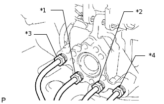
Connect the 4 brake lines to the correct positions of the hydraulic brake booster assembly as shown in the illustration.
Tip:*1: To front wheel cylinder RH
*2: To front wheel cylinder LH
*3: To rear wheel cylinder RH
*4: To rear wheel cylinder LH
Using a union nut wrench, connect the 4 brake lines to the hydraulic brake booster assembly.
15 N*m
155 kgf*cm
11 ft.*lbf
Note:Use the formula to calculate special torque values for situations where a union nut wrench is combined with a torque wrench (Click here).
Install the wiring harness bracket with the bolt.
8.0 N*m
82 kgf*cm
71 in.*lbf
Tip:Insert the end of the bracket into the hole when installing the bracket.
Attach the VSC connector to the wire harness clamp bracket.
Attach the clamp.
-
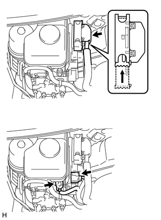
Connect the 3 connectors to the hydraulic brake booster.
INSTALL AIR INJECTION CONTROL DRIVER WITH BRACKET
INSTALL CANISTER
INSTALL FUEL FILTER ASSEMBLY
Install the fuel filter assembly (Click here).
INSTALL PUSH ROD PIN
INSTALL LOWER NO. 1 INSTRUMENT PANEL AIRBAG ASSEMBLY
Install the lower No. 1 instrument panel airbag assembly (Click hereClick here).
INSTALL ENGINE ROOM SIDE COVER LH
Install the engine room side cover LH with the 4 clips.
CONNECT CABLE TO NEGATIVE BATTERY TERMINAL
Note:When disconnecting the cable, some systems need to be initialized after the cable is reconnected (Click here).
BLEED BRAKE SYSTEM
CHECK AND ADJUST BRAKE PEDAL
Check and adjust brake pedal (Click here).
INSPECT BRAKE MASTER CYLINDER OPERATION
Inspect the brake master cylinder operation (Click here).
PERFORM YAW RATE AND ACCELERATION SENSOR ZERO POINT CALIBRATION
Perform yaw rate and acceleration sensor zero point calibration (Click here).