LIGHTING SYSTEM, Diagnostic DTC:B2430 and B2431
| DTC Code | DTC Name |
|---|---|
| B2430 | LED Headlight LH Circuit Malfunction |
| B2431 | LED Headlight RH Circuit Malfunction |
DESCRIPTION
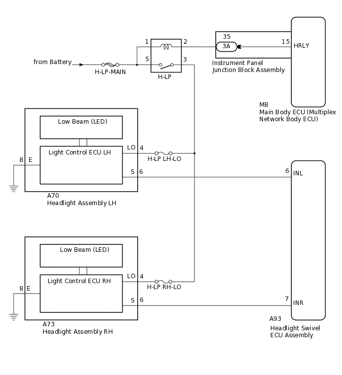
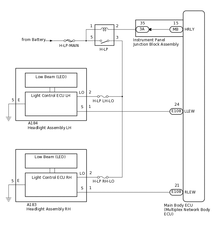
These DTCs are stored when the low beam headlights do not illuminate, or a malfunction is detected in the communication between the headlight assembly and headlight swivel ECU assembly*1 or main body ECU (multiplex network body ECU)*2.
*1: except Sedan
*2: for Sedan
DTC No. |
Detection Item |
DTC Detection Condition |
Trouble Area |
|---|---|---|---|
B2430 |
LED Headlight LH Circuit Malfunction |
LED headlight LH circuit malfunction |
|
B2431 |
LED Headlight RH Circuit Malfunction |
LED headlight RH circuit malfunction |
|
WIRING DIAGRAM
except Sedan
for Sedan
CAUTION / NOTICE / HINT
Inspect the fuses for circuits related to this system before performing the following procedure.
PROCEDURE
CHECK BODY TYPE
Check body type.
Result
Result
Proceed to
except Sedan
A
for Sedan
B
B CHECK FOR DTCClick here
CHECK FOR DTC
Clear the DTCs.
Body Electrical > AFS > Clear DTCs
Check for DTCs.
Body Electrical > AFS > Trouble Codes
Result
Result
Proceed to
DTC B2430 and B2431 are not output
A
Both DTC B2430 and B2431 are output
B
DTC B2430 or B2431 is output
C
C CHECK HARNESS AND CONNECTOR (HEADLIGHT ASSEMBLY - H-LP RELAY)Click here
INSPECT H-LP RELAY
-
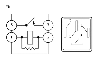
*a
Component without harness connected
(H-LP Relay)
Remove the H-LP relay from the engine room relay block and junction block assembly.
Measure the resistance according to the value(s) in the table below.
Standard Resistance
Tester Connection
Condition
Specified Condition
3 - 5
Voltage not applied between terminals 1 and 2
10 kΩ or higher
3 - 5
Voltage applied between terminals 1 and 2
Below 1 Ω
Result
Proceed to
OK
NG
NG REPLACE H-LP RELAY
-
CHECK HARNESS AND CONNECTOR (POWER SOURCE - H-LP RELAY)
Measure the voltage according to the value(s) in the table below.
Standard Voltage
Tester Connection
Condition
Specified Condition
Relay Terminal 1 - Body ground
Always
11 to 14 V
Relay Terminal 5 - Body ground
Always
11 to 14 V
Result
Proceed to
OK
NG
NG REPAIR OR REPLACE HARNESS OR CONNECTOR
CHECK HARNESS AND CONNECTOR (H-LP RELAY - HEADLIGHT ASSEMBLY LH AND HEADLIGHT ASSEMBLY RH)
Disconnect the A70 headlight assembly LH connector.
Disconnect the A73 headlight assembly RH connector.
Measure the resistance according to the value(s) in the table below.
Standard Resistance
Tester Connection
Condition
Specified Condition
Relay Terminal 3 - A70-4 (LO)
Always
Below 1 Ω
Relay Terminal 3 - A73-4 (LO)
Always
Below 1 Ω
Relay Terminal 3 - Body ground
Always
10 kΩ or higher
Result
Proceed to
OK
NG
NG REPAIR OR REPLACE HARNESS OR CONNECTOR
CHECK HARNESS AND CONNECTOR (H-LP RELAY - INSTRUMENT PANEL JUNCTION BLOCK ASSEMBLY)
Disconnect the 3A instrument panel junction block assembly connector.
Measure the resistance according to the value(s) in the table below.
Standard Resistance
Tester Connection
Condition
Specified Condition
Relay Terminal 2 - 3A-35
Always
Below 1 Ω
Relay Terminal 2 - Body ground
Always
10 kΩ or higher
Result
Proceed to
OK
NG
NG REPAIR OR REPLACE HARNESS OR CONNECTOR
INSPECT INSTRUMENT PANEL JUNCTION BLOCK ASSEMBLY
Remove the instrument panel junction block assembly.
for LHD:Click here
for RHD:Click here
Remove the main body ECU (multiplex network body ECU) from the instrument panel junction block assembly.
Measure the resistance according to the value(s) in the table below.
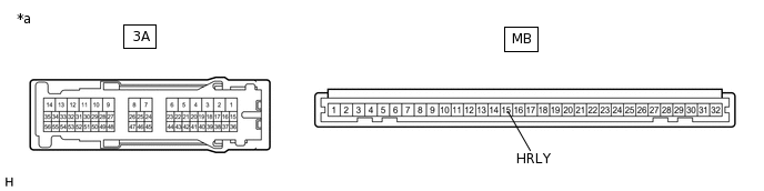
*a
Component without harness connected
(Instrument Panel Junction Block Assembly)
-
-
Standard Resistance
Tester Connection
Condition
Specified Condition
3A-35 - MB-15 (HRLY)
Always
Below 1 Ω
Result
Proceed to
OK
NG
CHECK HARNESS AND CONNECTOR (HEADLIGHT ASSEMBLY - H-LP RELAY)
Disconnect the A70 or A73 headlight assembly connector.
Measure the resistance according to the value(s) in the table below.
Standard Resistance
Table 1. LH Side (DTC B2430) Tester Connection
Condition
Specified Condition
A70-4 (LO) - Body ground
Light control switch in head position
11 to 14 V
Table 2. RH Side (DTC B2431) Tester Connection
Condition
Specified Condition
A73-4 (LO) - Body ground
Light control switch in head position
11 to 14 V
Result
Proceed to
OK
NG
NG REPAIR OR REPLACE HARNESS OR CONNECTOR
CHECK HARNESS AND CONNECTOR (HEADLIGHT ASSEMBLY - BODY GROUND)
Measure the resistance according to the value(s) in the table below.
Standard Resistance
Table 3. LH Side (DTC B2430) Tester Connection
Condition
Specified Condition
A70-8 (E) - Body ground
Always
Below 1 Ω
Table 4. RH Side (DTC B2431) Tester Connection
Condition
Specified Condition
A73-8 (E) - Body ground
Always
Below 1 Ω
Result
Proceed to
OK
NG
NG REPAIR OR REPLACE HARNESS OR CONNECTOR
CHECK HEADLIGHT ASSEMBLY (INPUT VOLTAGE)
Measure the voltage according to the value(s) in the table below.
Standard Voltage
Table 5. LH Side (DTC B2430) Tester Connection
Condition
Specified Condition
A70-6 (S) - Body ground
Ignition switch ON, light control switch in head position
4.5 to 5.5 V
Table 6. RH Side (DTC B2431) Tester Connection
Condition
Specified Condition
A73-6 (S) - Body ground
Ignition switch ON, light control switch in head position
4.5 to 5.5 V
Result
Proceed to
OK
NG
NG CHECK HARNESS AND CONNECTOR (HEADLIGHT SWIVEL ECU ASSEMBLY - HEADLIGHT ASSEMBLY)Click here
REPLACE HEADLIGHT UNIT
Replace the headlight unit with a new or known good one.
Check for DTCs.
Body Electrical > AFS > Trouble Codes
OK
DTC B2430 or B2431 is not output.
Result
Proceed to
OK
NG
OK END (HEADLIGHT UNIT WAS DEFECTIVE)
CHECK HARNESS AND CONNECTOR (HEADLIGHT SWIVEL ECU ASSEMBLY - HEADLIGHT ASSEMBLY)
Disconnect the A93 headlight swivel ECU assembly connector.
Measure the resistance according to the value(s) in the table below.
Standard Resistance
Table 7. LH Side (DTC B2430) Tester Connection
Condition
Specified Condition
A93-6 (INL) - A70-6 (S)
Always
Below 1 Ω
A93-6 (INL) - Body ground
Always
10 kΩ or higher
Table 8. RH Side (DTC B2431) Tester Connection
Condition
Specified Condition
A93-7 (INR) - A73-6 (S)
Always
Below 1 Ω
A93-7 (INR) - Body ground
Always
10 kΩ or higher
Result
Proceed to
OK
NG
NG REPAIR OR REPLACE HARNESS OR CONNECTOR
CHECK FOR DTC
Clear the DTCs.
Body Electrical > Main Body > Clear DTCs
Check for DTCs.
Body Electrical > Main Body > Trouble Codes
Result
Result
Proceed to
Both DTC B2430 and B2431 are not output
A
Both DTC B2430 and B2431 are output
B
DTC B2430 or B2431 is output
C
C CHECK HARNESS AND CONNECTOR (HEADLIGHT ASSEMBLY - H-LP RELAY)Click here
INSPECT H-LP RELAY
-
*a
Component without harness connected
(H-LP Relay)
Remove the H-LP relay from the engine room relay block and junction block assembly.
Measure the resistance according to the value(s) in the table below.
Standard Resistance
Tester Connection
Condition
Specified Condition
3 - 5
Voltage not applied between terminals 1 and 2
10 kΩ or higher
3 - 5
Voltage applied between terminals 1 and 2
Below 1 Ω
Result
Proceed to
OK
NG
NG REPLACE H-LP RELAY
-
CHECK HARNESS AND CONNECTOR (POWER SOURCE - H-LP RELAY)
Measure the voltage according to the value(s) in the table below.
Standard Voltage
Tester Connection
Condition
Specified Condition
Relay Terminal 1 - Body ground
Always
11 to 14 V
Relay Terminal 5 - Body ground
Always
11 to 14 V
Result
Proceed to
OK
NG
NG REPAIR OR REPLACE HARNESS OR CONNECTOR
CHECK HARNESS AND CONNECTOR (H-LP RELAY - HEADLIGHT ASSEMBLY LH AND HEADLIGHT ASSEMBLY RH)
Disconnect the A184 headlight assembly LH connector.
Disconnect the A183 headlight assembly RH connector.
Measure the resistance according to the value(s) in the table below.
Standard Resistance
Tester Connection
Condition
Specified Condition
Relay Terminal 3 - A184-2 (LO)
Always
Below 1 Ω
Relay Terminal 3 - A183-2 (LO)
Always
Below 1 Ω
Relay Terminal 3 - Body ground
Always
10 kΩ or higher
Result
Proceed to
OK
NG
NG REPAIR OR REPLACE HARNESS OR CONNECTOR
CHECK HARNESS AND CONNECTOR (H-LP RELAY - INSTRUMENT PANEL JUNCTION BLOCK ASSEMBLY)
Disconnect the 3A instrument panel junction block assembly connector.
Measure the resistance according to the value(s) in the table below.
Standard Resistance
Tester Connection
Condition
Specified Condition
Relay Terminal 2 - 3A-35
Always
Below 1 Ω
Relay Terminal 2 - Body ground
Always
10 kΩ or higher
Result
Proceed to
OK
NG
NG REPAIR OR REPLACE HARNESS OR CONNECTOR
INSPECT INSTRUMENT PANEL JUNCTION BLOCK ASSEMBLY
Remove the instrument panel junction block assembly.
for LHD:Click here
for RHD:Click here
Remove the main body ECU (multiplex network body ECU) from the instrument panel junction block assembly.
Measure the resistance according to the value(s) in the table below.
*a
Component without harness connected
(Instrument Panel Junction Block Assembly)
-
-
Standard Resistance
Tester Connection
Condition
Specified Condition
3A-35 - MB-15 (HRLY)
Always
Below 1 Ω
Result
Proceed to
OK
NG
CHECK HARNESS AND CONNECTOR (HEADLIGHT ASSEMBLY - H-LP RELAY)
Disconnect the A184 or A183 headlight assembly connector.
Measure the resistance according to the value(s) in the table below.
Standard Resistance
Table 9. LH Side (DTC B2430) Tester Connection
Condition
Specified Condition
A184-2 (LO) - Body ground
Light control switch in head position
11 to 14 V
Table 10. RH Side (DTC B2431) Tester Connection
Condition
Specified Condition
A183-2 (LO) - Body ground
Light control switch in head position
11 to 14 V
Result
Proceed to
OK
NG
NG REPAIR OR REPLACE HARNESS OR CONNECTOR
CHECK HARNESS AND CONNECTOR (HEADLIGHT ASSEMBLY - BODY GROUND)
Measure the resistance according to the value(s) in the table below.
Standard Resistance
Table 11. LH Side (DTC B2430) Tester Connection
Condition
Specified Condition
A184-5 (E) - Body ground
Always
Below 1 Ω
Table 12. RH Side (DTC B2431) Tester Connection
Condition
Specified Condition
A183-5 (E) - Body ground
Always
Below 1 Ω
Result
Proceed to
OK
NG
NG REPAIR OR REPLACE HARNESS OR CONNECTOR
CHECK HEADLIGHT ASSEMBLY (INPUT VOLTAGE)
Measure the voltage according to the value(s) in the table below.
Standard Voltage
Table 13. LH Side (DTC B2430) Tester Connection
Condition
Specified Condition
A184-1 (S) - Body ground
Ignition switch ON, light control switch in head position
4.5 to 5.5 V
Table 14. RH Side (DTC B2431) Tester Connection
Condition
Specified Condition
A183-1 (S) - Body ground
Ignition switch ON, light control switch in head position
4.5 to 5.5 V
Result
Proceed to
OK
NG
NG CHECK HARNESS AND CONNECTOR (MAIN BODY ECU (MULTIPLEX NETWORK BODY ECU) - HEADLIGHT ASSEMBLY)Click here
REPLACE HEADLIGHT UNIT
Replace the headlight unit with a new or known good one.
Check for DTCs.
Body Electrical > Main Body > Trouble Codes
OK
DTC B2430 or B2431 is not output.
Result
Proceed to
OK
NG
OK END (HEADLIGHT UNIT WAS DEFECTIVE)
CHECK HARNESS AND CONNECTOR (MAIN BODY ECU (MULTIPLEX NETWORK BODY ECU) - HEADLIGHT ASSEMBLY)
Disconnect the E108 main body ECU (multiplex network body ECU) connector.
Measure the resistance according to the value(s) in the table below.
Standard Resistance
Table 15. LH Side (DTC B2430) Tester Connection
Condition
Specified Condition
E108-24 (LLEW) - A184-1 (S)
Always
Below 1 Ω
E108-24 (LLEW) - Body ground
Always
10 kΩ or higher
Table 16. RH Side (DTC B2431) Tester Connection
Condition
Specified Condition
E108-21 (RLEW) - A183-1 (S)
Always
Below 1 Ω
E108-21 (RLEW) - Body ground
Always
10 kΩ or higher
Result
Proceed to
OK
NG
NG REPAIR OR REPLACE HARNESS OR CONNECTOR