PARKING BRAKE ASSEMBLY DISASSEMBLY

CAUTION / NOTICE / HINT
Note
-
When the brake pedal is first depressed after replacing the brake pads or pushing back the disc brake piston, DTC C1214 may be output. As there is no malfunction, clear the DTC.
-
While the auxiliary battery is connected, even if the power switch is off, the brake control system activates when the brake pedal is depressed or the door courtesy switch is turned on. Therefore, even if only brake pads are to be removed and installed, be sure to perform the Disable Brake Control procedure and disconnect the cable from the negative (-) terminal of the auxiliary battery before beginning work.
Tech Tips
-
Use the same procedure for the RH side and LH side.
-
The following procedure is for the LH side.
PROCEDURE
-
PRECAUTION
Note
After turning the power switch off, waiting time may be required before disconnecting the cable from the negative (-) auxiliary battery terminal, Therefore, make sure to read the disconnecting the cable from the negative (-) auxiliary battery terminal notice before proceeding with work Click here.
-
DISABLE BRAKE CONTROL
-
REMOVE REAR WHEEL
-
SEPARATE REAR DISC BRAKE CALIPER ASSEMBLY
-
REMOVE PARKING BRAKE SHOE ADJUSTING HOLE PLUG
-
REMOVE REAR DISC
-
REMOVE PARKING BRAKE SHOE RETURN TENSION SPRING (for Front Side)
-
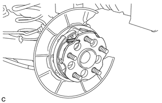
Remove the parking brake shoe return tension spring.
-
-
REMOVE PARKING BRAKE SHOE RETURN TENSION SPRING (for Rear Side)
-
Remove the parking brake shoe return tension spring.
-
-
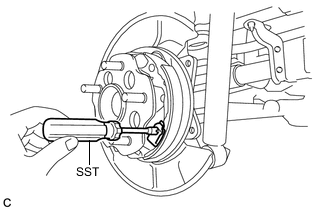
REMOVE BRAKE SHOE HOLD DOWN SPRING (for Front Side)
-
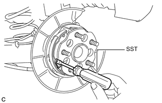
Using SST, remove the brake shoe hold down spring as shown in the illustration.
- SST
- 09718-00011
-
-
REMOVE PARKING BRAKE SHOE STRUT
-
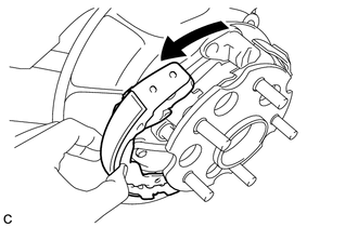
Pull the No. 1 parking brake shoe assembly towards the front of the vehicle by hand as shown in the illustration.
-
Remove the parking brake shoe strut.
-
-
REMOVE BRAKE SHOE HOLD DOWN SPRING (for Rear Side)
-
Using SST, remove the brake shoe hold down spring as shown in the illustration.
- SST
- 09718-00011
-
-
REMOVE PARKING BRAKE SHOE ADJUSTING SCREW SET
-
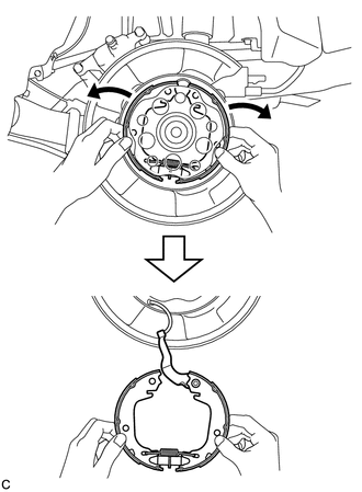
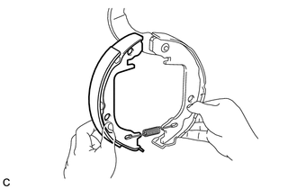
Expand the No. 1 and No. 2 parking brake shoe assemblies outward by hand and pull downward to separate them from the parking brake plate.
-
Remove the parking brake shoe adjusting screw set.
-
-
REMOVE NO. 1 PARKING BRAKE SHOE ASSEMBLY
-
Remove the No. 1 parking brake shoe assembly.
-
-
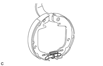
REMOVE PARKING BRAKE SHOE RETURN TENSION SPRING (for Lower Side)
-
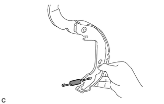
Remove the parking brake shoe return tension spring.
-
-
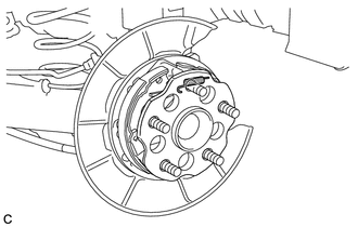
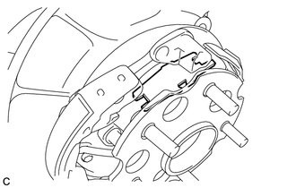
SEPARATE PARKING BRAKE SHOE LEVER
-
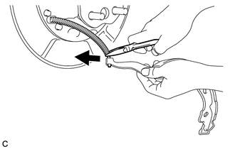
Using needle-nose pliers, separate the parking brake shoe lever from the No. 3 parking brake cable assembly as shown in the illustration.
-
-
REMOVE PARKING BRAKE SHOE LEVER
-
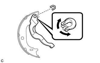
Using a screwdriver, remove the parking brake shoe type C washer, parking brake shoe shim and the parking brake shoe lever.
Tech Tips
Parking brake shoe shims are provided when necessary to adjust the clearance between the parking brake shoe lever and parking brake shoe type C washer. Some vehicles may not be equipped with shims.
-
-
REMOVE PARKING BRAKE SHOE HOLD DOWN SPRING PIN (for Front Side)
-
Remove the parking brake shoe hold down spring pin.
-
-
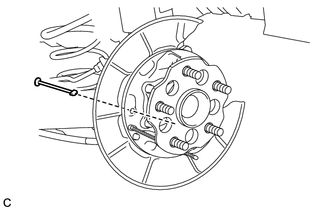
REMOVE PARKING BRAKE SHOE HOLD DOWN SPRING PIN (for Rear Side)
-
Remove the rear axle hub and bearing assembly Click here.
-
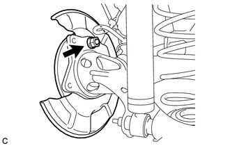
Remove the nut to separate the parking plate sub-assembly from the rear axle beam assembly.
Note
Hang the parking plate sub-assembly using a wire or an equivalent tool.
-
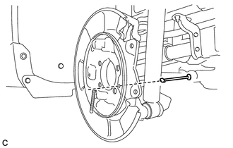
Remove the parking brake shoe hold down spring pin.
-