BACK DOOR CLOSER SYSTEM TERMINALS OF ECU
-
CHECK MULTIPLEX NETWORK DOOR ECU
-
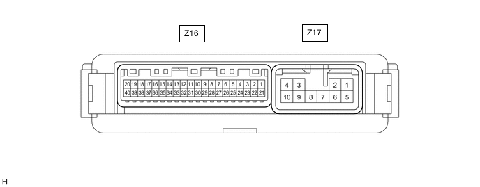
Disconnect the Z16 and Z17 multiplex network door ECU connectors.
-
Measure the voltage and resistance according to the value(s) in the table below.
Tech Tips
Measure the values on the wire harness side with the connector disconnected.
Terminal No. (Symbol) Wiring Color Terminal Description Condition Specified Condition Z16-20 (ECUB) - Body ground GR - Body ground Battery power supply Always 11 to 14 V Z16-18 (IG) - Body ground P - Body ground IG power supply Engine switch on (IG) 11 to 14 V Engine switch off Below 1 V Z17-1 (B) - Body ground Y - Body ground Battery power supply Always 11 to 14 V Z17-10 (GND) - Body ground W-B - Body ground Body ground Always Below 1 Ω -
Reconnect the Z16 and Z17 multiplex network door ECU connectors.
-
Measure the voltage and check for pulses according to the value(s) in the table below.
Terminal No. (Symbol) Wiring Color Terminal Description Condition Specified Condition Z17-4 (DC+) - Z17-3 (DC-) W - B Back door lock assembly (back door lock motor) circuit Back door lock motor operating 11 to 14 V Back door lock motor not operating Below 1 V Z16-11 (FUL) - Body ground V - Body ground Back door lock assembly (latch courtesy switch) signal circuit Back door closed → open Pulse generation → Below 1 V Z16-9 (HAF) - Body ground B - Body ground Back door lock assembly (half-latch switch) signal circuit Back door closed → fully open 11 to 14 V → Below 1 V Z16-7 (POS) - Body ground Y - Body ground Back door lock assembly (position switch) signal circuit Back door open → Back door closer operating → Back door closed Below 1 V → 11 to 14 V → Below 1 V
-
-
CHECK CERTIFICATION ECU (SMART KEY ECU ASSEMBLY)
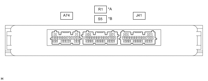
*A for LHD *B for RHD
-
Disconnect the J41 certification ECU (smart key ECU assembly) connector.
-
Measure the voltage and resistance according to the value(s) in the table below.
Tech Tips
Measure the values on the wire harness side with the connector disconnected.
Terminal No. (Symbol) Wiring Color Terminal Description Condition Specified Condition J41-4 (+B) - Body ground V - Body ground Battery power supply Always 11 to 14 V J41-18 (E) - Body ground W-B - Body ground Body ground Always Below 1 Ω -
Reconnect the J41 certification ECU (smart key ECU assembly) connector.
-
Measure the voltage and check for pulses according to the value(s) in the table below.
for LHD Terminal No. (Symbol) Wiring Color Terminal Description Condition Specified Condition R1-26 (TSW5) - Body ground G - Body ground Back door opener switch assembly signal Back door opener switch assembly (open switch) off Pulse generation Back door opener switch assembly (open switch) on Below 1 V for RHD Terminal No. (Symbol) Wiring Color Terminal Description Condition Specified Condition S5-26 (TSW5) - Body ground G - Body ground Back door opener switch assembly (open switch) signal Back door opener switch assembly (open switch) off Pulse generation Back door opener switch assembly (open switch) on Below 1 V
-