CONDENSER(for 8GR-FKS) INSTALLATION
CAUTION / NOTICE / HINT
Tech Tips
-
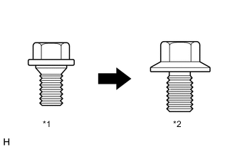
*1 Centering Bolt *2 Standard Bolt Centering bolts are used to mount the hood hinge to the vehicle body and hood. The hood cannot be adjusted with the centering bolts on. Substitute the centering bolts for standard bolts when making adjustments.
-
A bolt without a torque specification is shown in the standard bolt chart.
-
Use the same procedure for RHD and LHD vehicles.
-
The procedure listed below is for LHD vehicles.
PROCEDURE
-
INSTALL COOLER CONDENSER ASSEMBLY
-
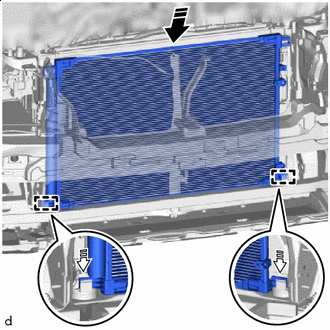

Install in the Direction 
Insert in this Direction Insert the cooler condenser assembly into the vehicle and into the guide.
Note
When inserting the cooler condenser assembly, do not damage the cooler condenser assembly and radiator assembly.
Tech Tips
If the cooler condenser assembly is replaced with a new one, add compressor oil to the new cooler condenser assembly.
Capacity 40 cc (1.35 fl.oz) Compressor Oil Refrigerant Compressor Oil HFC-134a (R134a) ND-OIL 8 or equivalent HFO-1234yf (R1234yf) ND-OIL 12 or equivalent -
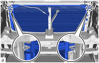
Attach the claw to install the cooler condenser assembly.
-
-
CONNECT DISCHARGE HOSE SUB-ASSEMBLY
-
Remove the vinyl tape from the discharge hose sub-assembly and the connecting part of the cooler condenser assembly.
-
Sufficiently apply compressor oil to a new O-ring and the fitting surface of the hose joint.
Compressor Oil Refrigerant Compressor Oil HFC-134a (R134a) ND-OIL 8 or equivalent HFO-1234yf (R1234yf) ND-OIL 12 or equivalent -
Install the O-ring to the discharge hose sub-assembly.
Note
Keep the O-rings and O-ring fitting surfaces free of foreign matter.
-
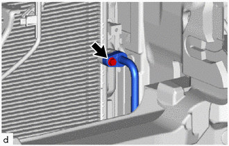
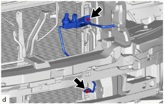
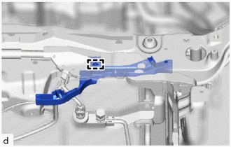
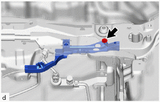
Connect the discharge hose sub-assembly to the cooler condenser assembly with the bolt.
- Torque:
- 5.4 N*m { 55 kgf*cm, 48 in.*lbf }
Note
-
Do not apply excessive force to the discharge hose sub-assembly.
-
Make sure not to cut the O-ring while installing it. (Cut O-rings cannot be installed)
-
-
CONNECT LIQUID TUBE SUB-ASSEMBLY A
-
Remove the vinyl tape from the liquid tube sub-assembly A and the connecting part of the cooler condenser assembly.
-
Sufficiently apply compressor oil to a new O-ring and the fitting surface of the tube joint.
Compressor Oil Refrigerant Compressor Oil HFC-134a (R134a) ND-OIL 8 or equivalent HFO-1234yf (R1234yf) ND-OIL 12 or equivalent -
Install the O-ring to the liquid tube sub-assembly A.
Note
Keep the O-rings and O-ring fitting surfaces free of foreign matter.
-
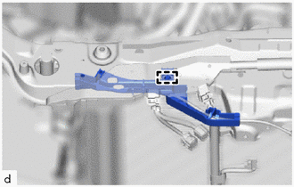
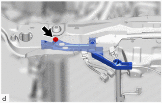
Connect the liquid tube sub-assembly A and No. 1 cooler bracket to the cooler condenser assembly with the 2 bolts.
- Torque:
- 5.4 N*m { 55 kgf*cm, 48 in.*lbf }
Note
-
Do not apply excessive force to the liquid tube sub-assembly A.
-
Make sure not to cut the O-ring while installing it. (Cut O-rings cannot be installed)
-
-
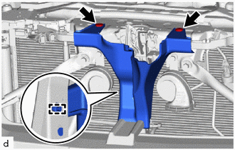
INSTALL UPPER RADIATOR SUPPORT SUB-ASSEMBLY
-
for LHD:
-
Attach the clamp.
-
-
Attach the clamp.
-
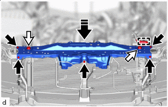

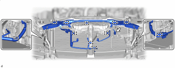
Bolt 
Sub-Radiator Support Cushion Install in this Direction Attach the upper radiator support sub-assembly to the 2 sub-radiator support cushions and install the upper radiator support sub-assembly with the 5 bolts as shown in the illustration.
- Torque:
- 12.5 N*m { 127 kgf*cm, 9 ft.*lbf }
Note
When installing the upper radiator support sub-assembly, do not damage the cooler condenser assembly and radiator assembly.
-
Attach the clamp.
-
for LHD:
-
Install the hood lock control cable cover LH with the screw.
-
-
Install the hood lock control cable cover RH with the screw.
-
Attach the clamp to connect the engine room main wire.
-
connect the connector.
-
-
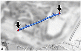
INSTALL RADIATOR SUPPORT TO CROSSMEMBER BRACE SUB-ASSEMBLY RH
-
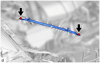
Install the radiator support to crossmember brace sub-assembly RH with the 2 bolts.
- Torque:
- 49 N*m { 500 kgf*cm, 36 ft.*lbf }
-
-
INSTALL RADIATOR SUPPORT TO CROSSMEMBER BRACE SUB-ASSEMBLY LH
-
Install the radiator support to crossmember brace sub-assembly LH with the 2 bolts.
- Torque:
- 49 N*m { 500 kgf*cm, 36 ft.*lbf }
-
-
INSTALL LOWER ARM BRACKET BRACE SUB-ASSEMBLY RH
-
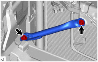
Install the lower arm bracket brace sub-assembly RH with the 2 bolts.
- Torque:
- 20 N*m { 204 kgf*cm, 15 ft.*lbf }
-
-
INSTALL LOWER ARM BRACKET BRACE SUB-ASSEMBLY LH
-
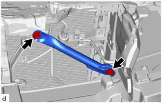
Install the lower arm bracket brace sub-assembly LH with the 2 bolts.
- Torque:
- 20 N*m { 204 kgf*cm, 15 ft.*lbf }
-
-
INSTALL LOW PITCHED HORN ASSEMBLY
-
INSTALL HIGH PITCHED HORN ASSEMBLY
-
INSTALL ENGINE HOOD COURTESY SWITCH (HOOD LOCK ASSEMBLY)
-
INSTALL HOOD LOCK RELEASE LEVER PROTECTOR
-
Attach the clamp.
-
Install the hood lock release lever protector with the 2 clips
-
-
INSTALL NO. 1 AIR CLEANER INLET
-
INSTALL HEADLIGHT ASSEMBLY RH
-
INSTALL POP UP HOOD LIFTER ASSEMBLY LH
-
INSPECT FITTING OF HOOD SUB-ASSEMBLY
-
ADJUST HOOD SUB-ASSEMBLY
-
CHARGE AIR CONDITIONING SYSTEM WITH REFRIGERANT
-
for HFC-134a(R134a):
-
for HFO-1234yf(R1234yf):
-
-
WARM UP ENGINE
-
for HFC-134a(R134a):
-
for HFO-1234yf(R1234yf):
-
-
INSPECT FOR REFRIGERANT LEAK
-
for HFC-134a(R134a):
-
for HFO-1234yf(R1234yf):
-
-
INSTALL LOWER RADIATOR AIR DEFLECTOR
-
INSTALL UPPER RADIATOR SUPPORT SEAL
-
INSTALL RADIATOR COVER PLATE